Mesoscopic Physics and Quantum Chaos
Mesoscopic Optics
Jens U.Nöckel
A worldwide rush is on to develop integrated optical components, aiming to increase data transmission rates and volumes in fiber optic networks in response to exponentially increasing demand. Of central importance to this 1.3 trillion US dollar market sector are dielectric microcavity resonators for use in photonic applications such as filters, multiplexers and lasers. Using semiclassical methods and tools from nonlinear dynamics, we analyze the spectral and emission characteristics of such open resonators.
Waveguiding and long-lived resonator modes
|
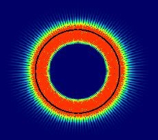
Extremely small, high-quality resonators
can be fabricated by exploiting total
internal reflection at the interface between a
circularly symmetric dielectric and the surrounding
air; see Fig.1 which shows the cross-sectional
intensity distribution of a long-lived photonic mode
in a dielectric disk. Classically forbidden
tunnel leakage across the rim (black line) leads only
to minute outcoupling losses which moreover are
isotropic. Coupling to such a resonator is very inefficient
unless another optical component
is brought extremely close to the rim so as to
overlap with the evanescent near field. This is not
amenable to highly reproducible device fabrication. An alternative and potentially much more efficient coupling mechanism is introduced when the rotational invariance of the resonator is broken, thus creating preferred emission directions, cf. Fig.2. Shown in false-color is the intensity of a long-lived mode as obtained from exact solution of Maxwell's equations. The green lobes extending into the far-field indicate the preferred directions along which coupling into or out of the resonator is now possible with great efficiency. |
Fig. 1 |
|
Shown at the bottom of Fig.2 is the classical ray picture corresponding to the wave solution depicted above. As indicated by the arrow, rays escape according to Snell's law after a number of total internal reflections because the angle of incidence is not conserved in the oval cavity. The wave solution mimicks this classical behavior and hence the emission directions as well as the lifetime of the mode can be predicted with the help of the ray picture. To establish the connection between rays and waves, semiclassical methods are required. |
Fig. 2 |
Phase space structure in the emission profile
|
The classical ray dynamics in general deformed
resonators exhibits a coexistence of periodic,
quasiperiodic and chaotic trajectories which is
difficult to disentangle by ray-tracing. A more
structured representation of the multitude of
different trajectories can be obtained by making
phase-space portraits. In this Poincaré
section, black dots represent individual reflections of
rays at the boundary, giving the position (polar angle
Superimposed onto the Poincaré section is a false-color density representation of a particular resonator mode. |
|
Fig. 3 |
| The high intensity around a chain of four islands of stability corresponds to a resonator mode associated with the corresponding stable motion. Its real-space intensity is shown in Fig. 4, where a bowtie-shaped pattern is apparent. The focussing inside and outside of the resonator is a desirable property that is achieved here by intentionally inducing the transition to partially chaotic ray dynamics. Oval lasers like the one shown here have been fabricated at Bell Labs and at less than 100 µm diameter (5.2 µm wavelength) delivered roughly 3 orders of magnitude more power than a comparable circular (non-chaotic) cavity. |
|
Fig. 4 |
More information can be found on my homepage