
This page is meant to be self-contained but can be read as part of an introduction to dielectric optical resonators which consists of these additional pages:
Like most of my web pages, the purpose here is is to highlight the central physics ingredients in some of my research by appealing to intuition and examples rather than mathematical derivations. This page is intended for people who may never have heard of differential equations, Bessel functions or group theory — but if you do have a background in these fields I still hope that you'll find the presentation thought-provoking.
Nowhere is the connection between geometry and physics more apparent than in musical instruments – tones are formed by vibrations whose wavelengths depend on the shape of the instrument. This can also be visualized. The movie (left) illustrates the vibrations of a circular drum as it resonates with a sound wave. We placed a baking pan upside down on a loudspeaker and poured some sand on it. As we play a loud sound at a continuously increasing pitch (frequency) through an amplifier, the sand is swept into varying formations.
At resonance, a standing wave of vertical displacement forms on the drum. The nodal lines (where the vibration amplitude is zero) form calm zones in which the sand accumulates. This makes the wave pattern visible. The German scientist Chladni is generally credited with the discovery of these patterns.
 What makes these "Chladni figures" fascinating is that they are determined purely by the geometric constraints on the resonating plate. Once that's fixed, all we have to do is find the right frequency f of excitation to get the vibration going, and we will reproducibly find a specific pattern (provided you control external factors like temperature). In our experiment, the perimeter is always a nodal line because the baking pan is creased and folded there, which makes it rigid so the boundary can't vibrate.
The nodal lines are stationary even though the rest of the plate is vibrating strongly. They are like a "fingerprint" of the resonating geometry. There are some frequency ranges where you don't observe much vibration at all despite the loud acoustic bombardment, and the sand remains almost motionless in the distribution it started out with. This is characteristic for a resonance phenomenon. The resonant vibration patterns are also called the "modes" of the plate.
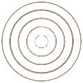
The concentric wave patterns clearly adher to the circular symmetry of the pan. The standing wave can be understoood as a radially outgoing wave that is reflected at the perimeter into an identical wave with radially inward-bound direction. Consequently, we can estimate the wavelength by simply measuring the distance from one nodal circle to the next-nearest circle.
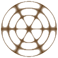
But not all modes look like concentric circles. Patterns similar to the one shown on the right can also be observed. You could call this a flower-petal shape.
The standing wave has radial nodal lines that come out from the axis in a star-shaped pattern. The spacing between the concentric circles is different from the spacing between the radial nodes, so it's not obvious how to determine "the" wavelength of this mode. It looks like there's a radial wavelength, and a different wavelength in the polar angle.
Nevertheless, even this type of mode does indeed have a well-defined overall wavelength, inversely proportional to the resonance frequency: λ = c/f (c is the speed of transverse waves on the plate, typically much smaller than the speed of sound in air). This is now merely a definition, not based on having equally spaced nodal lines. It's the wavelength that a plane wave of the given frequency would have in an infinite medium of the same material.
Looking at the radial and polar waves separately, the number of nodes in each direction is a measure of the distortion (or curvature) of the vibrating surface in that respective direction. I.e., modes with purely concentric patterns have no curvature in the polar direction. The vibration frequency of a mode is determined by the restoring force of the plate, which in turn depends on the surface curvatures in the radial and polar directions.
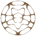
As a result, it so happens that a mode with 12 nodes in the polar direction and two nodes in the radial direction ends up having almost the same resonance frequency as a mode with just two polar nodes and four radial nodes. Two waves that have the same frequency are called degenerate.
What you see on the right is a superposition of these two (nearly) degenerate modes. In the vibrating plate experiment, they are able to resonate at the same audio frequency. The movie at the top sweeps through patterns like this in rapid succession as the frequency changes. You recognize such superposition states by the fact that their nodal patterns are not divisible into radial and polar directions.
So our experiment is also a hands-on confirmation of the superposition principle which states that for a medium with linear restoring forces, any two waves that oscillate at the same frequency can be added together to obtain another physically allowed wave with the same frequency but potentially very different nodal lines.
This is a very powerful statement because it allows us to decompose, or analyze, one wave pattern in terms of other patterns. We can even go so far as to view the concentric circular waves as superpositions of plane waves! A single plane wave can't form a standing-wave pattern in a circular enclosure because its wave fronts are planar and not round.
Still, the movie on the left illustrates that you can make circles out of planes by using the superposition principle. I'm simply adding a certain number of plane waves, each propagating with identical wavelength λ along one of the red arrows. The superposition creates interference patterns that take on a more and more circular shape, growing from the center, as the number of plane waves increases (the false-color plots are rescaled so that the center always has the same height, i.e., color. In this coloring scheme, wave crests are lightest and wave troughs are darkest).
If one of the concentric nodal lines happens to coincide with the radius of our circular plate, then the interior part of the plane-wave superposition exactly reproduces a resonant mode of the plate. The parts of the plane waves that fall outside of the radius make no difference: If the plate were infinite, the full plane-wave solution would be an acceptable wave solution, but it would still have a nodal line exactly where the perimeter of our actual plate would have been. So if we now imagine clamping down the plate along the nodal line and then cutting the outer parts off, the interior standing-wave pattern would remain unchanged. That's the same effect that one can observe on a guitar string when a finger lightly holds down the middle to create an overtone: you get a standing wave with a node in the middle which remains intact even after the finger is lifted.
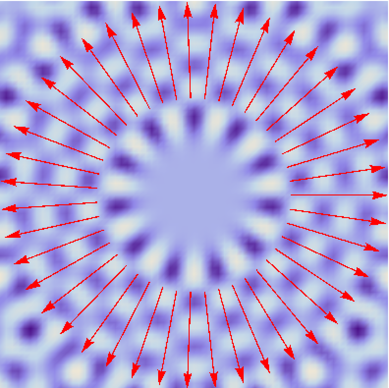
Again, the superposition principle can be used to understand such modes as a sum of plane waves. The image on the left shows 43 arrows, each indicating a plane wave rotated by a small angle increment. The difference to the earlier superpositions is that I also gave each plane wave a phase shift equal to m = 11 times its angular rotation. Finally, I chose the wave length shared by all plane waves to be just right to yield a nearly perfect circular nodal line right where the arrows have their starting points (λ = π/8× radius). This line defines the boundary of the resonator. The wave in that region looks like a wheel, with a purely circular standing wave. It's called a whispering-gallery mode.
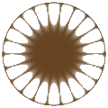
The new thing here is the number m which determines the number of nodes encountered going once around the circle (more precisely, twice that number). The phase shift it introduces in the superposition causes all the waves to exactly cancel in the center. The concentric nodal pattern is obtained for m = 0 which allows all waves to add constructively in the center, creating a wave crest there. Shown on the right is the corresponding nodal pattern as it would appear on a vibrating plate.
In terms of nodal lines, whispering-gallery modes are the extreme limit of the flower-petal shaped patterns above, where the number of radial nodal lines is much smaller than the number of nodes as a function of angle (also called aximuthal nodes). To get a perfectly circular nodal line on the assumed perimeter of our resonator, we would have to increase the number of superimposed plane waves to infinity; mathematically, this means going from a sum of plane waves to an integral.
The limit of infinitely many superimposed plane waves of wave length λ and phase-shift parameter m defines the Bessel function of order m, abbreviated in polar coordinates as Jm(k r). Here, k = 2π/λ is the wave number and r the radial distance from the origin. All the sand-colored nodal-line plots simulating the vibrating plate on this page were made by plotting the function Jm(k r) cos(m φ) where φ is the angle.
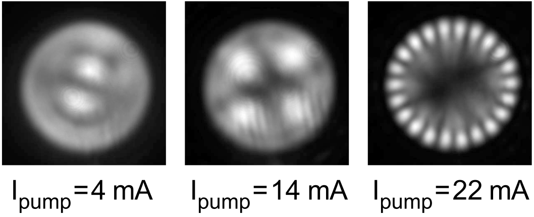
Modes very much like the above occur in optical physics as beam patterns produced by lasers. Lasers are typically designed to emit light of a single wavelength, and conventionally they also emit light with simple, regular nodal patterns. What you see on the left are some of the patterns that can occur in the cross-section of beams emitted by a VCSEL (vertical cavity surface emitting laser).
The images [from Gentsy et al., "Wave Chaos in Real-World Vertical-Cavity Surface-Emitting Lasers", Phys. Rev. Lett. 94, 233901 (2005)] show the top view of a circular optical resonator. For a review of that work (in German), see "Quantenchaos in neuer Optik". Intensity patterns reminiscent of the vibrating plate (recall the movie) are created here by light waves of slightly different wavelength which in turn arise when the laser is "pumped" with varying amounts of current. Special significance falls to the ring-shaped pattern at 22 mA: it has no radial nodes but many angular nodes, so we identify it as a whispering-gallery mode.
Lasers are based on a combination of feedback amplification and electromagnetic resonance. Some resonances respond more strongly to the external excitation than others – this depends on their losses. It turns out that we don't see whispering-gallery modes in the vibrating plate because their losses are too high. But in optical resonators, the situation is often exactly the opposite.
This is due to the boundary conditions on the surface of the resonator. Just like sound waves, optical waves can't easily be confined with perfect efficiency. There is always leakage. In optics, this creates the light emission characteristic of the resonant mode.
To say more about circular resonators in optics, we have to address the boundary conditions in more detail. This is explored on a separate page by juxtaposing rays versus waves. On that page, you'll also encounter the Archimedean spiral. If you look carefully through the images on this page, you should be able to spot a spiral pattern as well. Hint: look at the exterior part of a whispering-gallery mode!
Noli tangere circulos meos!
Do not disturb my circles! — held to be the last words of Archimedes of Syracuse.
But what if we do disturb the circle? The idealized Bessel-function solutions then no longer represent the resonant modes, and entirely new physics appears solely due to the change in boundary conditions. Nevertheless, we can still analyze the new modes using the superposition principle, either by building them up from plane waves, or by adding a potentially large number of Bessel-function solutions. This is the conceptual and computational starting point for much of my research listed in more detail on the overview page here.
When the boundary shape is strongly deformed away from a simple geometry such as the circle, we typically enter the regime of quantum chaos. Some of the visual effects in the opening credits of the Netflix series "The Lord of the Rings: The Rings of Power" illustrate how the nodal patterns on a chaotic vibrating plate change in real time as we vary the frequency. The basic physics that makes the grains of sand dance around and organize themselves into lines or rings is the same as what I described above.
This page © Copyright Jens Uwe Nöckel, 09/2012
Last modified: Sun Sep 25 19:40:52 PDT 2022


