
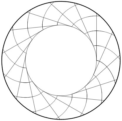
 If you have looked the Hitchhiker's Guide to Microlasers, you should have gotten the message that deformed, asymmetric optical resonators are much more interesting than symmetric ones, such as the circular shape shown here (uniform refractive index of n = 1.45 surrounded by air, where the wavelength is roughly half of the radius).
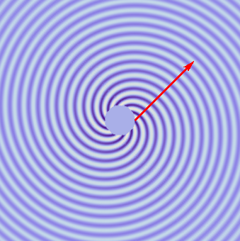
However, there is something disconcerting about the wave pattern for these supposedly simple systems — it's the asymmetry that manifests itself in the spiral arms emanating from the resonator. In the movies, the black circle delineates the boundary between the outside vacuum and the dielectric in which the light is generated. But the circular geometry has no asymmetry, and neither does the medium. So what causes the appearance of a "handedness" in my wave plots?
On this page I will explain what's going on here. I've been asked about this a couple of times, even by experts. To some extent this is because people haven't been plotting metastable states the way I am here. In fact (to my knowledge), nobody had made such plots for chaotic cavities before my work on directional whispering-gallery emission. Thus, these patterns have an element of surprise when you look at instantaneous wave amplitudes as we are doing here. The amplitude of the electric field emanating from a circularly symmetric microlaser is shown in false-color representation, with white for zero amplitude. On this page, chaos plays no role because we're looking only at circular dielectric resonators.
If you want a reference for the basic idea behind the spiral wave fronts in optical resonators, I would first point you to my dissertation [1], where I show an analogous picture for the inside of the resonator in figure 7.3 (reproduced on the left), and provide additional references. There is ample prior work on this topic, dating back to the sixties, and I won't list it all here.
The same material as in my thesis (slightly more condensed) has been published in the form of a book chapter [2].
A very detailed analysis for the spherical dielectric, including the coupling to free space, is found in [3].
A set of color plots for various modes of the sphere can be found in figures 2 and 3 of [4].
Eigenmodes of spherical dielectric cavities: coupling of internal and external raysJ. Opt. Soc. Am. A 16: 882--895, 1999.
This page is concerned with the field outside the cavity, in particular with the approximate form of the wave field discussed in section 9.18 of my dissertation [1] and section 7.2.2 of [2]. The spirals in the figure on the left are the wave fronts, and they are shown together with a family of straight-line rays that are everywhere perpendicular to these wave fronts. This ray-wave correspondence is crucial to understanding the patterns you see in the movies.
The wave fields shown in the movies are obtained by solving the equations in section 8.2 of [1].
 The wave solutions in a closed resonator are discussed with some examples on this page on circular resonators.
There, you'll also find a conceptual introduction to Bessel functions, Jm, which play an important role on this page.
The reason why there is an asymmetry in this problem is the openness of the resonator, which we take into account by imposing radiation boundary conditions. The constant flux of radiation from the resonator to infinity makes this problem different from the standard exercise of finding the modes of a closed circular domain (the math is identical for a wide range of appplications: from the electromagnetic waves of a flat, round standing-wave cavity to the natural vibrations of a drum). Our optical resonators are open because the dielectric boundary is not an ideal mirror for the light trapped on the inside.
In the closed resonator of refractive index n, the wave pattern ψ is fully described by
 Here, we have made use of the circular symmetry by introducing polar coordinates r, φ. We'll discuss the dependence on angle φ first, and come back to the r dependence later. I am using the Greek symbol ψ (psi) for the electric field because everything I'm writing here in principle also applies to the magnetic field, so a more familiar name like E doesn't capture the generality of the argument.
The polar angle enters the solution through a complex exponential with an "azimuthal quantum number" m that counts how many wave periods fit around the perimeter of the circle; so m must be an integer to guarantee single-valuedness of the wave. Whenever you see a complex exponential of an angle in a wave solution, it is a mathematical way of expressing rotational symmetry; but to make a plot of the wave we always revert to real-valued functions by taking the real part of ψ. This is allowed because the wave equation we are dealing with satisfies the superposition principle.
When you take the real part of a complex exponential, the result is a cosine function. The wave will therefore have the angular dependence cos(mφ), leading to a radial pattern of high-and low intensity ridges. You can see this in the second movie shown on the right (at wavelength approximately one-fifth of the radius) which corresponds to an almost isolated cavity mode: The intensity on the inside (much higher than outside, as indicated by the color) is described by the azimuthal cosine function just mentioned. I.e., the interior nodal lines do not show any spiral pattern.
The radial coordinate r enters the interior field as the argument of a Bessel function Jm. Just as sine functions can describe a standing wave pattern on one-dimensional string, Bessel functions describe two-dimensional standing waves (see this page for an introduction). Such waves typically have "holes" in the middle, as is indicated by the blank central regions in the movies. This is what makes the waves look like whispering-gallery modes. The wave number k is a real number, but there is in fact an infinite set of possible k which are then enumerated by another integer similar to m, the "radial quantum number" (for the purposes of this page, explicit notation to that effect isn't needed). This set of k is determined by the condition that the Bessel function must vanish on the boundary of the circle (assuming that the closed resonator is formed by an ideal mirror).
The above form of the solution remains valid for the open resonator, except that k ends up being quantized at different, complex values. In addition to this relatively minor modification (which we neglect here, see this paper for additional discussion), there is now a whole new region of space in which we must write down the corresponding wave pattern: the space outside the circle. It is connected to that on the inside by the conditions of continuity for the electromagnetic field. The solution on the outside (i.e., for radial coordinates r larger than the radius of the circle) is
where H(1)m is the Hankel function of the first kind and A is a proportionality constant.
The appearance of the Hankel function instead of the Bessel function is caused by the radiation boundary condition. Physically, this condition comes from the fact that we're looking for wave patterns that transport energy outward as time progresses. The time variable is of course already incorporated in the movies, although the playback speed has been artificially slowed so that the movies don't give you vertigo (I hope). To put the time t into these solutions, all you have to do is to replace mφ by mφ–ckt everywhere, where c is the speed of light.
To see that the Hankel function gives us the desired radiation behavior, use its asymptotic form at large r, which lets us write the time-dependent wave as one single complex exponential:
If we now take the real part, as is done for the exact wave solution in the movies, the asymptotic wave will again be a cosine function, whose zeros occur wherever the argument is an odd multiple of ninety degrees. Choosing just ninety degrees as the phase angle, the condition for this phase can be written as follows:
As t increases, the combination of r and φ on the left must increase proportionally. This means that the curve described by this equation moves out toward larger distances, as is expected for a radiation pattern.
At any given time t, this equation relates the coordinates r and φ to define a curve in the plane. This curve is the Archimedean spiral — it can be brought into the form r(φ) = a φ + b:
In this form, you also see that the radial distance in a fixed direction φ increases at the speed of light, as it should.
The spiral appears in the phase fronts of the outside wave because both the radial and angular coordinates, r and φ, enter in a "traveling-wave" fashion, encoded in the complex exponential. Taking the real part, we end up with both coordinates inside a cosine. In the closed cavity, on the other hand, the radial coordinate enters in a "standing-wave" fashion and only yields a radial modulation of the azimuthal wavefronts when the transition from complex exponential to cosine is made.
So far, the technical reasons I have sketched above will make sense mainly to readers who have at least a vague idea why Bessel functions are the correct description for the modes in a circular resonator. But there is an even easier way to understand the spiral patterns. It's so easy that you don't have to know anything about Bessel functions at all.
This is, of course, the ray picture that I already alluded to in the box with my references. All you need to know is that rays are perpendicular to wave fronts. This important fact establishes a rigorous connection between the spiral arms of our movies and families of rays that are escaping from the resonator.
In the picture on the left, I have drawn the interleaving Archimedean spirals as seen in the first movie (just using a larger plot area and a simpler color scale), and then added a red line that remains perpendicular to all the spiral arms it intersects. This represents an escaping ray. The further out we go, the more the spiral arms look like concentric circles, and the ray then appears to be coming from the center of the plot. But if you look closely at the neighborhood of the circle in the center, it becomes clear that the requirement of being perpendicular to the spiraling wave fronts forces the ray to maintain a nonzero offset (impact parameter) from the center.
This offset is proportional to the angular momentum of the ray. The emission from a whispering-gallery mode launches the rays like a slingshot, and the spiral is a necessary consequence of the resulting off-center straight-line trajectories.
The disk in the center of the picture represents the dielectric resonator cavity; it is left "blank" because I was only interested in the wave fronts outside the cavity. Recall that the Archimedean spiral arises when we make an asymptotic approximation, which for the Hankel and Bessel functions means that the argument should be much larger than the index (m).
You may ask what happens if instead of a dielectric, the disk is a perfect conductor, where we can still create waves outside of the disk and let them be scattered by the conducting obstacle. In that case the electric field must vanish on the perimeter, and the outside field is found to contain rays that are propelled out from the perimeter in a precisely tangential direction. Such waves are well-known under the name "creeping waves." They can be derived by starting from exactly the same Hankel function H(1)m(kr) eimφ given above, and using a slightly different approximation called the "approximation by tangents" (Debye approximation).
To create a family of tangents to a circular perimeter, imagine unrolling a string of yarn from a cylindrical spool. The geometric construction corresponding to this process is called the involute of the circle, and its wave fronts yield a spiral that approxiates the Archimedean spiral at large distance. In optics, if a wave front describes the involute of a curve (like the circle), then that curve is called a caustic. At caustics, the rays are bundled together very densely, leading to strongly enhanced intensity.
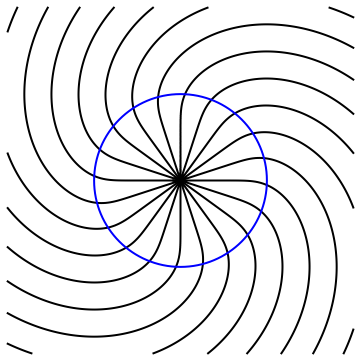
The asymptotic (large-distance) approximation always has to be replaced by the Debye approximation if we are sufficiently close to the caustic. This is why near the resonator, the wave fronts deviate from the Archimedean ideal. At some finite distance from the center, they become perpendicular to the perimeter as in the creeping waves mentioned above. The picture on the left shows this by plotting the zeros (nodes) of the real part of H(1)m(kr) eimφ without approximations (if you read the above discussion, you should be able to infer what value of m I chose in the plot). The blue circle is the dividing line between kr < m and kr > m.
It's obvious that the inside of the blue circle doesn't look like an Archimedean spiral at all. In terms of the foregoing discussion, this is because the radial wave loses its traveling-wave character. This is of course what allows the outside field to connect smoothly to the inside field (which is described by the Bessel function, not the Hankel function). Physically, the inside looks different from the outside because reflection at the boundary causes two wave fronts with opposite radial direction (but same sense of rotation) to appear. The two waves interfere to cause the pattern of straight nodal lines. In the interference pattern of this example, it's hard to pinpoint where exactly the caustic is, but you can tell it's somewhere inside the resonator. In the movies on this page, the interior caustic is the dividing line between the whispering-gallery waves and the essentially field-free region near the center.
 This scenario is especially important to keep in mind when taking a closer look at the second movie earlier on this page. You can tell that the spiral arms in that movie don't show any curvature until they are well outside the circle. What this means is that there is a region just outside of the resonator where there is no radially traveling wave! But there is a radially traveling wave further away from the resonator. Unlike the caustic on the inside of the circle, this can't have been caused by interference with a reflected wave, because there is only free space in that region.
The light must have leaked from the inside of the resonator to the traveling-wave region of free space by crossing a "forbidden zone" in which the wave fronts indicate that there is no outward-traveling ray. This seemingly contradictory phenomenon is the optical analogue of quantum tunneling. Yes, this is not quantum mechanics, but the term "tunneling" is in no way unique to quantum systems. It can essentially be found in all wave equations where a classical (short-wavelength) limit exists.
The existence of a tunnel barrier between outside and inside is crucial for the lifetime of the cavity mode. Shown at right is an animation that shows the connection between the two earlier movies.
Displaying just one quarter of the circular resonator, we change the wavelength and azimuthal quantum number (m) to make a smooth transition between the weakly confined mode that initially led us to the Archimedean spiral, to a strongly confined mode that displays a tunnel barrier.
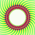
In this magnified plot, you can see the alternating patterns of high and low instantaneous amplitude in the color coding. The color scale is as follows: ![]() .
Use the movie playhead to scroll betwen the frames. In the last frame, the nodal lines (white) start bending into spirals only after they have crossed to the exterior of the circle.
.
Use the movie playhead to scroll betwen the frames. In the last frame, the nodal lines (white) start bending into spirals only after they have crossed to the exterior of the circle.
It is important to keep in mind that all these pictures show one and the same dielectric resonator. All we're doing is to look at different modes, with different wavelengths (here described in terms of wavenumbers k) and with different angular momenta (proportional to m). Among all these different coexisting modes, it is generally the longest-lived ones that are of greatest interest and physical significance. The longest lifetimes in circular resonators are ideally limited purely by tunneling.
The last movie on the left leads to the somewhat provocative conclusion that tunneling is essentially a "classical phenomenon," in the sense that it is the violation of a ray-optics expectation, and was given a special name only because that expectation is considered the basis of our understanding. The expectation is that a ray emanating from the resonator should in some way be traceable back to the surface of that resonator. But if you take the red arrow as a ray and require it to be perpendicular to the numerically calculated wave fronts, a forbidden region is revealed in which no rays can propagate.
To see this, use the playhead slider of the movie to adjust the arrow until it is perpendicular to the wave fronts near the top right (that's far enough from the surface so that ray expectations will be valid). This will put the playhead shortly before the middle of the movie. At that stage, there is no way to trace the arrow all the way back to the black circle which delineates the resonator (the high-intensity colors have been omitted to make the circle easier to see). And no — bending the rays isn't allowed because if there's one thing that classical ray optics tells us is that rays in free space are straight lines!
This "disconnect" between the far-field ray and the surface means that the ray appears to be originating from a point outside of the circle, but in a tangential direction. The offset is of the order of the wavelength, so it will become insignificant in the short-wavelength limit.
This is what I meant when I claimed tunneling is a classical phenomenon: the wave does whatever waves do, but the rays don't quite behave as we expect them to. If we didn't insist on using a ray description, we wouldn't need the concept of tunneling.
This page © Copyright Jens Uwe Nöckel, 2011-2018
Last modified: Mon Nov 19 11:49:38 PST 2018


