|
We report the surprising observation of highly directional light emission from nearly spherical fused silica optical resonators, in which most of the phase space is filled with non-chaotic regular trajectories. The observed emission pattern, along with a theoretical analysis, shows that non-perturbative phase space structures in the internal ray dynamics profoundly affect tunneling leakage of the whispering gallery modes. |
Electromagnetic fields in a uniform dielectric sphere can be calculated in much the same way as quantum mechanical wave functions in a spherically symmetric potential. The sphere exhibits whispering-gallery (WG) modes, which are long-lived resonances with electromagnetic fields confined near the surface [1]. For small deviations from the spherical shape, ε≡(rmax - rmin)/(rmax + rmin) « 1 (where rmax, rmin are the maximal and minimal radii), perturbative treatments [2] are routinely employed to infer deformation parameters from the splitting of azimuthal degeneracy of the WG modes [3]. Certain strongly non-spherical resonators, on the other hand, can be analyzed with methods from quantum chaos such as random-matrix theory or periodic-orbit expansions [4]. Many generic resonator shapes, however, fall into a transition regime in which none of these known methods apply globally. When entering this regime from the perturbative side, calculations may encounter singularities and undefined limits [5]. Experimental studies in this regime can thus provide insight into how nature resolves the competition between perturbative and non-perturbative physics, here with the resonator shape as a control parameter.
In this paper we present studies of far-field emission patterns and resonance lifetimes of deformed fused-silica microspheres at various degrees of deformation. Highly directional emission from WG modes with Q-factors (proportional to the modal lifetime) near 108 is observed from microspheres with ε ≈ 1% and with the size parameter kR = 2πR/λ ≈ 785 ( λ ≈ 800nm, R ≈ 100μm). These results are completely unexpected in the ray optics limit or in the earlier perturbative wave treatment with ε as a small parameter. The observed emission pattern illustrates how the non-perturbative phase space structure in the internal ray dynamics can profoundly affect tunneling leakage of the WG modes. Directional emission patterns have previously been observed only in more strongly deformed resonators where a significant fraction of the internal rays shows chaotic motion [6] and consequently the Q-factors are much smaller than reported here.
Deformed microspheres were formed by melting together two spheres of similar sizes. The individual spheres were fabricated by melting an optical fiber tip with a focused CO2 laser beam. The spheres were brought into contact and heated until surface tension produced a completely convex surface. By carefully controlling the temperature of the glass using the CO2 laser, it was possible to repeatedly reduce the degree of deformation. For reference, we define the elongated axis of the resulting prolate spheroid, which also connects the centers of the two original spheres, to be the x-axis. The z-axis is defined by the remaining fiber stem, which breaks the rotational symmetry about the x-axis, making the deformed microsphere completely non-axisymmetric. Images of these deformed microspheres taken from three orthogonal directions have been shown in an earlier study [7].
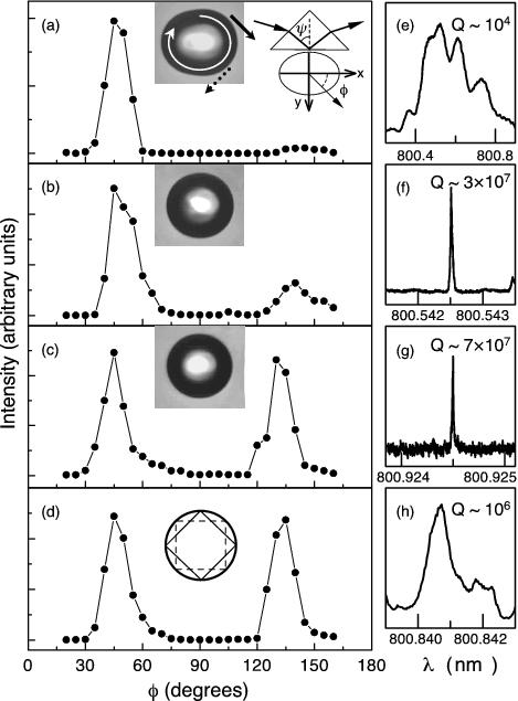
To investigate emission properties and resonance lifetimes of the deformed microspheres, we use frustrated total internal reflection at the surface of a prism with refractive index n = 1.7 to launch individual traveling-wave WG modes near the x-y plane of the spheroid (Fig. 1a inset). The measurement was performed with a tunable diode laser (New Focus). In this approach, the initial angle of incidence χ0 inside the microsphere with which the WG modes were launched can be controlled by adjusting the angle of incidence ψ inside the prism.
WG mode spectra were obtained by measuring the far-field emission intensity as a function of the excitation wavelength. Since the stem holding the resonator is a strong leakage pathway, the observed long-lived WG modes exhibit minimal amount of scattering near the stem region and thus must have internal field patterns that do not overlap with the stem region. This is made possible by the fact that the resonator is slightly flattened in the z direction (along the stem axis). Experiments as well as ray simulations show that this deformation stabilizes the rays in the vicinity of the x-y plane. Our directionality measurements correspondingly were performed in this plane. By scanning the detector while keeping the resonator fixed, we recorded WG mode spectra at various angles, φ (from the x-axis), from which we constructed the far-field emission pattern at a given microsphere deformation ε. The microsphere was then reheated to reduce the degree of deformation and the far-field emission pattern was measured again. Figure 1 shows the evolution of the measured far-field emission pattern of a microsphere as its deformation is reduced. The excitation beam is s-polarized, and the detection scheme is polarization-insensitive. The far-field emission patterns are independent of the polarization of the excitation laser beam.
Beginning with a strongly deformed microsphere, the emission was observed to have a strong peak at φ= 45o in the far field [see Fig. 1 (a)]. Since clockwise traveling waves were excited, as indicated by the white arrow in the sphere image in Fig. 1 (a), this far-field emission direction corresponds to light escaping tangential from the region at φ= -45o on the surface of the microsphere, shown by the solid arrow in the sphere image. A much smaller peak (5% of the large peak height) in the far-field emission pattern was observed at φ= 135o, corresponding to light escaping from the region at φ= 45o on the microsphere surface (dotted arrow). As the deformation was reduced, the far-field emission peak at φ= 135o grew to about one quarter of the φ= 45o-peak height in Fig. 1 (b). In Fig. 1 (c), the two peaks reached nearly equal intensity. The bright emission spots at φ= ± 45o on the resonator surface can be viewed directly with a CCD camera. For reference, we call the pattern in Fig. 1 (a) asymmetric and the pattern in Fig. 1 (c) symmetric (around φ= 90o). Figures 1 (e)-(g) also show that as the deformation was reduced, the Q-factor of the relevant WG modes increased by nearly four orders of magnitude.
The measurements discussed thus far were performed with input condition χ0 ≈ 90o (sinχ 0 ≈ 1). Figure 1 (d) shows the far-field emission pattern from the same microsphere as Fig. 1 (c) but with light launched at sinχ 0 ≈ 0.8. The emission pattern is nearly identical to Fig 1 (c) where sinχ0 ≈ 1, although the corresponding Q-factor is nearly two orders of magnitude smaller [Figs. 1 (g) and (h)].
The observed emission patterns in Fig. 1 (a)-(d) disagree with the intuitive expectation that WG modes in an oval resonator should preferentially emit tangential to the points of highest curvature, into the far-field direction φ= ± 90o. This is what one obtains when modeling our spheroids as triaxial ellipsoids, whose internal ray dynamics exhibits no chaos [8], independently of the axis ratios.
The observed emission pattern of the most deformed microsphere, Fig. 1 (a), is well explained by a ray model. The peak at φ= 45o can be attributed to an effect known as dynamical eclipsing [6]. In the ray model, a WG mode corresponds to light rays trapped close to the perimeter of the dielectric resonator by total internal reflection, which prevents light escape unless a critical angle χc≡ arcsin 1/n = 43.6o is reached, where n = 1.45 is the refractive index of the fused silica. At small but finite ε, any oval can be approximated by the first terms of a multipole expansion, which after proper choice of origin is quadrupolar. In this limit, a stable 4-bounce orbit shaped like a diamond forms with its sharp vertices at the highest-curvature points of the resonator with an angle of incidence χ4 ≈ 45o [inset to Fig. 1 (d)]. In the phase space describing the possible types of ray motion [4], this creates “islands of stability”: rays launched near the diamond orbit will retain similar reflection points and angles even if they do not close onto themselves after four bounces. Chaotic rays, which exponentially diverge from trajectories with closely neighboring initial conditions, cannot penetrate the diamond-shaped 4-bounce islands. At the deformation used in Fig. 1 (a), most of the phase space supporting the WG mode in question is chaotic. However, since χ4 ≈ χc chaotic WG rays are prevented from refractively escaping at the points of highest curvature. Instead, as trajectories flow around the islands in one direction, refractive escape occurs near φ= -45o on the resonator surface. From this circulation around the islands, asymmetric far-field emission patterns result as a hallmark of refractive escape. This is what we observe in Fig. 1 (a).
This ray mechanism was originally proposed and tested for effectively 2D systems where islands of stability and chaotic regions are mutually exclusive. In our 3D spheroids, the same diamond-shaped stable orbit exists in or near the x-y plane, and refractively escaping rays in its vicinity have lifetimes that correspond to ≤ 10 round trips in the resonator, translating to a Q-factor near 104. During this time, a given ray can be considered as moving in a cross-sectional plane that may be inclined and slowly precessing around the z-axis. The variation of cross-sectional shape, Δ ε, probed by such rays causes no significant differences in the size of the 4-bounce islands [9, 10]. Therefore, chaotic rays in the 3D resonator behave as in a corresponding fixed 2D resonator during a relatively short time scale preceding an escape event, and in particular avoid islands of stability, leading to dynamical eclipsing.
However, refractive escape ceases to be the dominant leakage mechanism at the very small deformation used in Figs. 1 (c) and (d), since in this case chaotic diffusion is no longer effective and the stable diamond orbit itself also becomes fully confined by total internal reflection. In addition, ray simulations neglecting tunneling escape cannot produce the symmetric emission patterns observed in Figs. 1 (c) and (d) [11]. The symmetric emission in Figs. 1 (c, d) reveals the importance of tunneling as a correction to the ray picture, as discussed below.
Tunneling becomes the only decay mechanism in an ideal sphere where each WG mode in the plane of excitation corresponds to a unique azimuthal angular momentum number m with respect to the z-axis, which is semiclassically related to the angle of incidence by sinχ0 = m/(nkR), using the fact that the modes of interest remain close to the x-y plane and hence have total angular momentum l ≈ m. At kR » 1, the tunneling escape rate is negligible when sinχ 0 ≈ 1 but accelerates exponentially as sinχ 0 approaches sinχ c. In a deformed microsphere, the angle of incidence χ varies as function of φ. χ(φ) is a well-defined function of φ provided it covers an angular momentum range where chaos is neglibible [12]. A circulating ray with varying χ(φ) >χ c will then escape with exponentially strong selectivity near the minima of χ(φ).
The emission locations and directions observed in the experiment indicate that the minima of χ(φ) should lie near the corners of the unstable rectangular 4-bounce orbit [inset to Fig. 1 (d)]. We determined from ray tracing that this only occurs near but above χc. Thus, the symmetric far-field patterns in Figs. 1 (c) and (d) are a tunneling probe for the minima of the ray-optical χ(φ) in the vicinity of the critical angle χc. To further corroborate this interpretation, recall that the emission patterns as shown in Figs. 1 (c) and (d) are insensitive to the initial angle of incidence, χ0, as they should be if the detected light originates near sinχ ≈ sinχ c. The question remains how the light coupled into the resonator is able to reduce its angular momentum from a high value corresponding to sinχ0 to the much lower sinχ c. Our observation shows that such a dynamical process is present in the spheroid, but does not unambiguously reveal its mechanism. A possible mechanism is Arnol’d diffusion, a phase-space transport process that crucially depends on the fact that the resonators are in fact three-dimensional [7], with no axial symmetry. While this exceedingly slow process can lead to very long lifetime, we defer a discussion of these truly 3D effects to a future publication [10], and focus instead on the phase space regions that are near sinχ c and are responsible for the observed emission patterns.
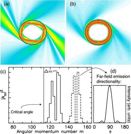
Figures 2 (a) and (b) plot the numerical results of the intensity patterns of two WG modes under traveling-wave excitation [12, 13]. The calculation assumes s-polarized light, uses size parameters near kR ≈ 113 [14], and models the shape felt by modes in the x-y plane as the cross section of a quadrupolar cylinder. This 2D model is justified by the 3D ray simultions discussed earlier: the emission patterns probe ray motion near the critical angle on relatively short time scales over which deviations from a planar dynamics are negligible.
|
|
The emission patterns in Figs. 2 (a) and (b) agree qualitatively with the asymmetric and the symmetric emission patterns shown in Figs. 1 (b) and (d), respectively. To understand the physical mechanism for the emission in Fig. 2 (b), we plot in Fig. 2 (c) the distribution of angular momentum numbers for the WG mode in (b). As shown in Fig. 2 (c), there is negligible overlap with the window for refractive escape below the critical angle χc, which in this plot translates to a critical angular momentum mc = kR ≈ 113. This indicates that the emission from this mode is due to tunneling escape. By comparison, both refractive and tunneling escape contribute to the emission in Fig. 2 (a), with the refractive escape playing a dominant role.
The peak splitting of width Δm ≈ 4 in Fig. 2 (c) is a straightforward consequence of the oval deformation: as the wave circulates around the resonator with varying radius between rmin and rmax, its angular momentum oscillates but has high probabitity of being near its extrema, given by the extrema of m ≈ r(φ)nkR sinχ(φ) over the surface. The fact that the minima of χ(φ) do not occur at φ= 0o, 180o on the surface is due to the 4-bounce island structure in the vicinity of sinχ = sin 45o.
For comparison, Fig. 2 (c) also shows the distribution of angular momentum number of an ultra-high Q WG mode with emission directionality as expected for the ellipse [see Fig. 2 (d)]. The mode is confined at a high m, corresponding to sinχ 0 ≈ 0.91. Note that here the tunneling loss is negligible compared with other loss mechanisms such as scattering or absorption loss of the material that limits the actual Q-factor of fused silica microspheres to of order 109 [15]. The two modes in Fig. 2 (c) have practically no overlap in angular momentum space. The qualitative difference in the far-field patterns of these two modes further confirms that the mode shown in Fig. 1 (c), which was excited at sinχ 0 ≈ 1, is not confined to sinχ0 ≈ 1.
In essence, our experiment exploits the peculiar feature that for fused silica the critical angle lies near the phase-space islands corresponding to the stable 4-bounce orbit. These islands are the dominant structure in the WG region and persist even at small ε where most of the phase space is filled with non-chaotic, “regular” trajectories. The island formation is a non-perturbative consequence of the breakdown of conservation laws [8], which qualitatively distinguishes the generic quadrupolar shape from an ideal ellipse even though the two shapes differ only to second order in ε. The emission characteristics of a silica spheroid in the seemingly trivial small-ε regime will continue to be strongly affected by ray patterns that wrap around the perimeter in approximately four bounces.
Whether any non-perturbative structure in the ray dynamics can be resolved by the wave field, depends on the size parameter kR [16]: a directionality measurement will be able to distinguish the peaks at φ= 90o ± 45o if the conjugate angular momentum m satisfies the uncertainty relation Δφ Δm ≥ 1/2 with Δφ ≈ π/4. This implies Δm > 2/π ≈ 1, which in our spheroids translates to a fluctuating angle of incidence of Δsinχ =Δ m/(nkR) ≈ 10-3. Even the least deformed resonator (ε ≈ 1%) exceeded this estimated resolution threshold significantly.
It is truly remarkable that these peculiar properties, for which chaos plays no dominant role, can be exploited to engineer WG modes that can feature both high-Q and highly directional emission. This makes WG resonators with small deformation highly promising for a variety of applications [17], such as microlasers, nonlinear optics, and quantum information processing.
This work was supported in part by NSF under grants No. DMR9733230 and No. DMR0201784.
[1] L. G. Guimaraes and H. M. Nussenzveig, J. Mod. Opt. 41, 625 (1994); G. Roll and G. Schweiger, J. Opt. Soc. Am. A 17, 1301 (2000).
[2] S. Ng, P. Leung, and K. Lee, J. Opt. Soc. Am. B 19, 154 (2002); and references therein.
[3] W. von Klitzing et al., Opt. Lett. 26, 166 (2001).
[4] H.-J. Stöckmann, Quantum Chaos, An Introduction (Cambridge University Press, 1999).
[5] M. V. Berry, Phys. Today 55 (May), No. 5, p. 10 (2002).
[6] S. Chang et al., J. Opt. Soc. Am. B 17, 1828 (2000).
[7] S. Lacey and H. L. Wang, Opt. Lett. 26, 1943 (2001).
[8] H. Waalkens, J. Wiersig, and H. R. Dullin, Ann. Phys. 276, 64 (1999).
[9] S. S. Chang, N. B. Rex, and R. K. Chang, J. Opt. Soc. Am. B 16, 1224 (1999).
[10] D. H. Foster and J. U. Nöckel (2002), unpublished.
[11] Even at small deformation, the separatrix region we are probing is created by the homoclinic tangle of the unstable, rectangle-shaped periodic orbit shown dashed in the inset to Fig. 1 (d), and this tangle exhibits an asymmetry which will produce asymmetric emission whenever the escape is predominantly ray-based [10].
[12] J. U. Nöckel and A. D. Stone, Nature 385, 45 (1997).
[13] I. Braun et al., Appl. Phys. B 70, 335 (2000).
[14] We have performed the same calculations at wave numbers kR ≈ 70, and close to the current limits of our numerical technique at kR ≈ 200. All these results are consistent with the ones presented in Fig. 2, showing that the phase-space structure causing the observed emission is already fully resolved in Fig. 2. Extrapolating to the experiment (Fig. 1) at kR ≈ 785, we expect no further changes within the angular resolution of the detector apparatus.
[15] M. L. Gorodetsky, A. A. Savchenko, and V. S. Ilchenko, Opt. Lett. 21, 453 (1996).
[16] R. E. Prange, R. Narevich and O. Zaitsev, Phys. Rev. E 59, 1694 (1999)
[17] S. M. Spillane, T. J. Kippenberg and K. J. Vahala, Nature 415, 621 (2002); and references therein.