BasicCAD Review -Starting to Draw

Last Updated: 04/01/01 02:46 PM

Week 1, Session 2


Concept of Commands

Three ways to do the same thing


  • Pulldown menu - select from a list
  • Toolbar -click a button
  • Command line - type the name of the command

    Shortcuts at the command line ("z" = ZOOM, etc.)


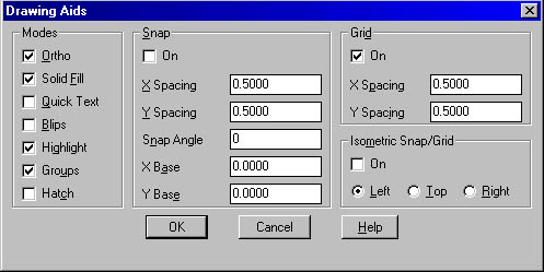
Adjusting SNAP and GRID

To pull up the drawing aids window, go to Menu>Tools>Drawing Aids...

As you work, you can turn the grid and Snap mode on and off, and you can change the grid and snap spacing.

The grid is a pattern of dots that extends over the area you specify as the drawing limits. Using the grid is similar to placing a sheet of grid paper under a drawing. The grid helps you align objects and visualize the distances between them. The grid is not plotted. If you zoom in or out of your drawing, you may need to adjust grid spacing to be more appropriate for the new magnification.

Snap mode restricts the movement of the crosshairs to intervals that you define. When Snap mode is on, the cursor seems to adhere, or "snap," to an invisible grid. Snap is useful for specifying precise points with the arrow keys or the pointing device. You control snap precision by setting the X and Y spacing.

Snap spacing does not have to match grid spacing. For example, you might set a wide grid spacing to be used as a reference but maintain a closer snap spacing for accuracy in specifying points.

Changing the Snap Angle and Base Point

If you need to draw along a specific alignment or angle, you can change the snap angle. This rotation realigns the crosshairs on the screen to match the new angle. In the following example, the snap angle is adjusted to match the angle of the anchor bracket.

When you set the snap angle, the grid rotation also changes.

The snap base point is the offset from a specified X,Y value from which snap points are measured. The default snap base point is 0,0, but it can be changed to any X,Y coordinate value to adjust snap points.

For example, if X and Y spacing are set to 0.5, and X and Y base points are set to 0,0, the snap points along the X and Y axes are 0, .50, 1.0, and so on. Changing the X snap base point to 0.1 and the Y snap base point to 0.2 causes the snap points along the X axis to shift to 0.1, 0.60, 1.1, and so on, and the snap points along the Y axis to shift to 0.2, 0.7, 1.2, and so on. Shifting the snap base point may be necessary to align a hatch pattern.

Drawing with Accuracy
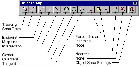
 

To enter a polar coordinate (2D)

  • At a prompt for a point, enter the coordinate using the following format:

    distance<angle

  • Distance represents the distance from the origin (0,0).
  • Angle represents the degree of angle from the origin (0,0).
  • Use the @ sign to make the entered coordinate relative to the last point:

@distance<angle

To enter a relative Cartesian coordinate (2D)

  • At a prompt for a point, enter the coordinate using the following format: @x,y
  • X represents the distance and direction along the horizontal axis from the last point entered. Y represents the distance and direction along the vertical axis from the last point entered.

To draw a line using direct distance entry

  1. Start the LINE command and specify the first point.
  2. Move the pointing device until the rubber-band line extends at the same angle as the line you want to draw.
  3. Specify a distance on the command line and press ENTER.


The line is drawn at the length and angle you specified

Using Object Snaps


Use Object Snaps to "snap" to a specified part of existing objects.  For example, use the "Endpoint" object snap to snap to the endpoint of a line. We'll discuss these in greater detail next week.

Drawing Simple Objects
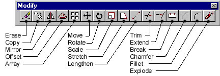


  • Use the LINE tool to draw straight line segments.
  • Use the ARC tool to draw arc segments of a circle
  • Use the CIRCLE tool to draw circles.  The default method of drawing a cicle is to pick a center and a radius.  It is also possible to pick 2 points, 3 points, or 2 tangents and a radius.
  • Use the RECTANGLE tool to draw a connected rectangle.  Even though the rectangle appears to be made up of four line segments, it is in fact a POLYLINE and as such, a connected, single entity.
  • To end a command, either hit return, use the right mouse button, or the ESC key.

Modifying Toolbars


  • To open a toolbar go to View>Toolbars... and check the bar you want to open.
  • Toolbars can be dragged onto the drawing window and made to "float"
  • Floating toolbars can be dragged to edges of drawing window to "dock"
  • Click the little "X" in the upper right corner of a floating toolbar to close it.


Simple Modifications to Objects

Simple Modify commands – menu or toolbar: 
  • ERASE, 
  • COPY, 
  • MOVE, 
  • ROTATE, 
  • OFFSET, 
  • FILLET, 
  • MIRROR

Reading: Frey, Skill 2

Freycover.gif (14149 bytes)

Syllabus