Last Updated: 05/14/01 09:29 PM
Week 8 Review Questions (answers at end of page):
A. What are grips? How do you use them in AutoCAD r14? [Answer]
B. What is an insertion point? [Answer]
C. What is regeneration and when would you need to force AutoCAD to REGEN? [Answer]
D. What is a linetype scale? How would you make your linetypes display the same way in Paper Space viewports of different scales? How would you make a linetype such as BATTING display correctly in different viewports of the same model? [Answer]
E. If you want to make select objects in AutoCAD more like a Macintosh, that is to press and drag a box, and to use the shift key to add or subtract objects from a selection set, how do you do that? [Answer]
Navigation in 3-D drawings:
From AutoCAD's On-Line help:
Controlling the User Coordinate System (UCS)
In AutoCAD, there are two coordinate systems: a fixed system called the World Coordinate System (WCS), and a movable system called the user coordinate system (UCS). In the WCS, the X axis is horizontal, the Y axis is vertical, and the Z axis is perpendicular to the XY plane. The origin is where the X and Y axes intersect (0,0) in the lower-left corner of the drawing. You define a UCS in terms of the WCS. Virtually all coordinate entry uses the current UCS.
Moving the UCS can make it easier to work on particular sections of your drawing. Rotating the UCS helps you specify points in three-dimensional or rotated views. Snap, Grid, and Ortho modes all rotate in line with the new UCS.
You can relocate the user coordinate system using any of these methods:
- Move the UCS by defining a new origin
- Align the UCS with an existing object or with the current viewing direction
- Rotate the current UCS around any of its axes
- Restore a saved UCS
Once you have defined a UCS, you can name it and then restore it when you need to use it again. The Prev option of the UCS command sequentially restores up to 10 previous coordinate systems used in the current session. If you no longer need a named UCS, you can delete it. Also, you can restore the UCS to be coincident with the WCS.
Setting Drawing Planes in 3D (UCS)
AutoCAD provides two coordinate systems: a fixed coordinate system called the World Coordinate System (WCS) and a moveable coordinate system called the user coordinate system (UCS). The UCS is useful for entering coordinates, defining drawing planes, and setting views. Changing the UCS does not change your viewpoint. It changes only the orientation and tilt of the coordinate system.
If you are creating 3D objects, you can relocate the UCS to simplify your work. For example, if you have created a 3D box, you can edit each of its six sides easily by aligning the UCS with each side as you edit it.
You relocate a UCS by choosing the location of the origin point and the orientation of the XY plane and the Z axis. You can locate and orient a UCS anywhere in 3D space. Only one UCS is current at any given time, and all coordinate input and display is relative to it. If multiple viewports are active, they share the same UCS.
If you plan to work extensively in 3D, you can save by name UCS locations, each having a different origin and orientation, for various construction requirements. You can relocate, save, and recall as many UCS orientations as you require.
Working with the World and User Coordinate Systems in 3D
When drawing in 3D, you specify X, Y, and Z coordinate values in either the World Coordinate System (WCS) or the current user coordinate system (UCS). The illustration below shows the X, Y, and Z axes of the WCS.

The WCS and the UCS are often coincident – their axes and origin points overlap exactly. No matter how you reorient the UCS, you can always make it coincident with the WCS by using the World option of the UCS command.
Applying the Right-Hand Rule

Use the right-hand rule to determine the positive axis direction of the Z axis when you know the direction of the X and Y axes in a 3D coordinate system. You can also use the right-hand rule for determining the positive direction of rotation about an axis in 3D space.
UCS Command: Origin/ZAxis/3point/Entity/View/X/Y/Z/Prev/REstore/Save/Del/?<World>:
- Origin: defines new UCS by shifting the origin of the current UCS. leaving the direction of it's X,Y, and Z axis unchanged.
- ZAxis: used to define a new UCS that has a particular extrusion direction. This determines X and Y axis for you based on the new Z axis.
- 3point: Allows you to establish a UCS by first clicking on the origin of the new UCS, then a point on the positive X axis, then a point on the positive y axis.
- Object: Defines a new UCS by pointing to an object (no 3D polylines, meshes or viewports). The new UCS will have the same positive Z orientation as that of the selected object and will have the same positive X orientation as the sequence of points selected in developing that entity.
- View: A new UCS is set parallel to the screen. Origin remains the same.
- X/Y/Z:: rotate UCS around a given axis. Enter the angle you want to rotate. For example, rotating 90 degrees around X axis will leave the positive Y axis pointing out of you screen.
- Save: Save the current UCS with name you provide. Very important to save UCS's so that you can easily get back to the objects you create with them.
- <World>: Return to the World Coordinate System. Just hit return.
Displaying the Model:
- Multiple views of the same model. Menu>View>Tiled Viewports... Differences and similarities between Model space viewports and paper space viewports.
- Using 3D viewport presets to see the same thing from different angles:
- Use Named Views... on the Menu bar to save and restore saved views.
UCS Icon: The Icon is not displayed at the true origin of the current coordinate system. The "W" tells you that you are in the World Coordinate system.
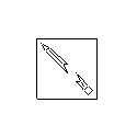
The "+" shows that the icon is displayed at the origin of the current coordinate system. No box will appear if the positive Z distance is pointing away from you (into the screen). The broken pencil icon is displayed when you are viewing the model parallel to the XY plane of the current UCS. In this case, you cannot draw new objects. To draw again, change the UCS or your view.
Creating 3-D geometry:
Tools to create 3-D objects:
- Use EXTRUDE to create 3-D object from 2-D polyline. The Path sub-option allows you to select a polyline to be used as an extrusion "path". <Height> asks you to specify an extrusion height. Positive numbers will extrude in the positive Z of the CURRENT UCS. Be careful to correctly set the UCS prior to extruding. Negative extrusion heights will extrude in the negative Z direction. Enter a taper angle if you want one. Positive taper angles taper towards Z, negative away.
- Use the 3-D toolbars to create 3-D objects directly.
Solids cannot be stretched, but may be subtracted and unioned together. They may be filleted and Sliced (3-D trimming).
Surfaces are hollow, they may be stretched and computed (3D meshes and revolved surfaces).
Displaying your Model:
Hiding, Shading and Rendering:
- Use Hide to see only surfaces that are not covered by others in current view. Text will not hide unless it is given some thickness. The fastest way to see what's what.
- Use Shade to apply simple shading to the surfaces of your model. AutoCAD calculates the surfaces angle relative to a default light source and applies shading accordingly. Use with Shadedge and Shadedif variables to adjust appearance.
- Use Render to produce more realistic images. Apply textures or AutoCAD uses layer color for rendering. Be careful since large drawings can take a long time to render.
Review Question Answers:
![]()
Reading: Frey, Appendix A

