![]()
Last Updated: 04/01/01 11:14 PM
LA 408/508 Intermediate CAD Workshop * Review
Various Useful Commands:
Getting Around Back to Top... Command Button Toolbar Description PAN Standard ZOOM REALTIME Standard ZOOM WINDOW Standard Creating Objects Back to Top... Command Button Toolbar Description LINE Draw CONSTRUCTION LINE (XLINE) Draw POLYLINE Draw POLYGON Draw RECTANGLE Draw ARC Draw CIRCLE Draw HATCH Draw MULTILINE TEXT Draw Modifying Objects Back to Top... Command Button Toolbar Description ERASE Modify COPY Modify MIRROR Modify OFFSET Modify MOVE Modify ROTATE Modify SCALE Modify STRETCH Modify TRIM Modify EXTEND Modify BREAK Modify CHAMFER Modify FILLET Modify EXPLODE Modify Layers Back to Top... Command Button Toolbar Description LAYER Object Properties PROPERTIES Object Properties Information Back to Top... Command Button Toolbar Description DISTANCE Standard or Inquiry LIST Standard or Inquiry AREA Standard or Inquiry
Variables Back to Top... Variable Translation Description The variables listed below can be typed in at the command prompt. Most of these variables control settings in the program that are also changed in dialog boxes.
DIMLFAC Dimension Linear Factor PSLTSCALE Paper Space Linetype Scale PLINEWID Polyline Width
Utilities Back to Top... item Type Description Coordinate Filters (Point Filters)
Keyboard entry during selection. Or Use OSNAP menu by holding SHIFT key and clicking RIGHT mouse button Example:
LINE From point: .X of MID of <Select an object>
(need YZ) MID of <Select another object>
To point: <Specify another point>
Direct Distance Entry Combination of keyboard and mouse point entry. With direct distance entry, you can quickly specify a point relative to the last point you entered. At any AutoCAD prompt for a point location, you first locate the cursor to specify the direction and then enter a numeric distance.
In this example above, the second point for the line will be located 5 units toward the direction of your cursor. The direct distance that you enter is measured along the path from the last point to the current location of the cursor. This feature is usually used with Ortho or Snap mode turned on.
Example:
LINE From point: Specify a point
To point: Move cursor in the desired direction and enter
Review Questions from Previous Classes: Back to Top...
A. Name three ways of starting a command. Answer B. Name two ways to check the area of a building plan. Answer C. Name two ways to change an object's layer. Answer D. What would you use Paper Space for and how would you "get there?" Answer E. What is Associative Hatch? Let's say you have an area of your drawing that has just the right hatch pattern in it. What is the easiest way to duplicate that pattern? Answer
A. How would you create a new text style and change current drawing text to that style? Answer B. If you receive a drawing from a collegue or consultant that is drawn in decimal feet and you wish to convert it to architectural units, what would you do? Answer C. If a linetype (dashed, for example) appears too small, that is the dashes are too small and close together, what can you do to fix it? Answer D. You insert a detail bubble block with attributes (text) and forget to enter the values at the time of insertion. Now you want to go back and add the text. How do you do that? Answer E. You have drawn both roof and floor plan information in a single model. In Paper Space you created two viewports. Both show all the model layers and are not displayed to scale. What should you do to create a 1/4" floor plan and a 1/8" roof plan? Answer
A. You don't know on which layer a red line on your screen resides. How do you find out? Answer B. You dimension an object in Paper Space and the number displayed is MUCH smaller than the size at which you drew the object. What do you do to fix it? Answer C. You want to freeze a layer of an XREF but you don't know the name of the layer. What can you do? Answer D. You insert a object such as an Xref or Block but when you are done with the insert command, your screen looks the same. What are two possible problems and what do you do to fix them? Answer E. The drawing you were given does not have the correct dimension style. What is the easiest way to make the current drawings style match your "standard". Answer
A. What are grips? How do you use them in AutoCAD r14? Answer B. What is an insertion point? Answer C. What is regeneration and when would you need to force AutoCAD to REGEN? Answer D. What is a linetype scale? How would you make your linetypes display the same way in Paper Space viewports of different scales? How would you make a linetype such as BATTING display correctly in different viewports of the same model? Answer E. If you want to make select objects in AutoCAD more like a Macintosh, that is to press and drag a box, and to use the shift key to add or subtract objects from a selection set, how do you do that? Answer
![]()
Review Question Answers:
A. Name three ways of starting a command:
- Menu at top of AutoCAD window (File, Edit, View, Insert, etc...)
- Toolbar buttons.
- Command Line. Here you have to type the name of the command exactly or type a keyboard shortcut such as "L" for "LINE". Shortcuts are customizable and many experienced AutoCAD users take advantage of that.
B. Name two ways to check the area of a building plan:
- Draw polyline, list its properties: Draw a polyline (PLINE command or Draw toolbar) around area to be checked. Be sure the pline is closed by either typing a "C" instead of the last mouse-click or by PEDITing the polyline and typing "C" for close. Next, LIST (Inquiry toolbar) the properties of the newly created PLINE. At the end of the information that displays you should see the area listed in the current drawing units (hint: if the area listed is not in the units you were expected you are not drawing in the units you tought you were...)
- AREA command: Use AREA command (Inquiry toolbar) and click points around the perimeter of the area in question. The command returns the area enclosed by your clicks in the current units. See hint above.
Back to Questions C. Name two ways to change an object's layer:
- Properties Command: Start Properties command, select object in question, pick "Layer..." option and then chose the layer to which you wish to change. Click OK until you're done. This process works for single objects at a time.
- Click object, change layer in Layer Control window: Without starting a command, click on the obect in question--object should highlight and most likely "grips" should appear at corners. Next, on Object Properties toolbar (if not open, use Menu>View>Toolbars... to open it) notice that the dispaly changes from the current layer to the layer of the object on which you just clicked (if different...). To change the layer, click on the Layer Control window which causes it to "drop-down" with a display of all the layers currently in your drawing (and not filtered out!). Choose the layer you want. You're done.
D. What would you use Paper Space for and how would you "get there?"
- Paper Space is useful for displaying your model for printing. It allows you to open "viewports" into Model Space where your drawing usually resides. By scaling the viewports as needed, you can organize a sheet of drawings at different scales and views while keeping you model simple and clean. Also, you can add text and dimensions in Paper Space that will float over the Model Space viewport below. To "get there" double-click on the "TILE" button on the status bar at the bottom of the AutoCAD window (looks like: SNAP, GRID, ORTHO, OSNAP, MODEL, TILE). If you can't see it, try maximizing the AutoCAD window. You can also "get there" by setting the system variable TILEMODE to 0, which is what the button-clicking described earlier is doing for you.
E. What is Associative Hatch? Let's say you have an area of your drawing that has just the right hatch pattern in it. What is the easiest way to duplicate that pattern?
- Associative Hatch is a fill pattern that automatically updates when its boundary changes. If associativity is removed from the hatch, the fill pattern will not update. Once removed, associativity cannot be restored.
- Inherit Properties in the Boundary Hatch dialog box. This option allows you to select a hatch pattern that you wish to match and then imports the fill patterns to the current settings.
A. How would you create a new text style and change current drawing text to that style?
- Create the Style: Use Menu>Format>Text Style... In the dialog box that appears click New. Give your new style a name (may be helpful if Style name is close or matches actual font name). Click ok. In the Font Name pull down window select the font you wish to assign to the new style. A preview of the font should appear in the lower right corner. Once you like it, click apply, then Close.
- Change the Properties: Next, click either Menu>Modify>Properties... or the Properties button on the Object Properties toolbar and select the text you wish to change. A Modify text (or Mtext) dialog box pops up. In this dialog box change the Style from its current setting to the one you just created. You're done.
Back to Questions B. If you receive a drawing from a colleague or consultant that is drawn in decimal feet and you wish to convert it to architectural units, what would you do?
- Change the Units: Use Menu>Format>Units... and select Architectural. While you're in the dialog box you might also consider checking the precision to make sure it's what you want.
- Scale the drawing: Since Architectural units are ALWAYS IN INCHES you need to scale the entire drawing by the number of architectural units in each decimal foot, or by 12. First make sure all layers are THAWED. Frozen layers will not be modified. Use the Scale button on the Modify toolbar (or use menu...), when prompted to select objects, type all or drag a window around everything. Hit return to stop selecting things and then type 12 followed by return. You're done.
Back to Questions C. If a linetype (dashed, for example) appears too small, that is, the dashes are too small and close together, what can you do to fix it?
- Change the Objects Linetype Scale: Using the Properties command (Menu>Modify>Properties...) change linetype to a larger number. Remember that if you have the system set up to use paper space units for scaling (Layer and Linetype Properties>Linetype tab>Details...) then objects whose linetype seems small in MODEL space, my view correctly in PAPER space. You'd have to toggle into Paper Space (doubl-click TILE on Status Bar) and view the object through a viewport. I know, it's stupid.
- Change the global linetype scaling variable: Use Menu>Format>Linetype... press Details... and change the global scale factor. Or type LTSCALE at the command prompt and enter the value you want. If you were to print from Model Space, you would set the LTSCALE to the plotscale. For example, if you were going to plot a quick 1/4" scale view of your floor plan and didn't want to set up a layout in paper space, you could set LTSCALE to 48 (1 plotted unit to 48 drawing units--remember to convert to inches) and your object's linetypes would scale correctly.
Back to Questions D. You insert a detail bubble block with attributes (text) and forget to enter the values at the time of insertion. Now you want to go back and add the text. How do you do that?
- Modify Attribute: Either use Menu>Modify>Object> Attribute>Single... or the Edit Attribute button on the Modify II toolbar, or type DDATTE and the command line. Click the block whose text you want to change. In the dialog box that appears, enter the appropriate changes, then click O.K.
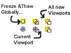
Back to Questions E. You have drawn both roof and floor plan information in a single model. In Paper Space you created two viewports. Both show all the model layers and are not displayed to scale. What should you do to create a 1/4" floor plan and a 1/8" roof plan?
- Freeze and Thaw layers to correctly display the information: In the veiwport to be the floor plan, freeze all roof plan information. To do this, either click Menu>Format>Layer or click in the pull-down window on the Object Properties toolbar. Find all layers with the word "roof" in them and freeze them IN THE CURRENT VIEWPORT which is different from freezing them globally, or in future new viewports.
Back to Questions
Next, switch to your other viewport and do the same for the floor plan layers. Do not freeze layer "0" or layer "Defpoints" since doing that may cause your Paper Space viewports to disappear.
Back to Questions
- Scale the viewports: Either use the zoom command or MVSETUP. To use the ZOOM command, first drop into floating model space by double-clicking on the PAPER button on the status bar. Next choose Menu>View>Zoom...>Scale or type ZOOM at the command window. Now enter the scale factor-- it is a relationship between Model Space units and Paper Space units. To show the floor plan at 1/4" = 1'-0" the relationship is 1 Paper Space unit to 4x12 Model Space units (remember everything must be converted to inches) or 48. Therefore type 1/48xp. The "xp" tells the computer the relationship involves paper space. If you want to use MVSETUP, type the command at the command prompt, choose the option of "S" for Scale Viewports, select the viewport you want to scale, and enter the same relationship described above. For the Roof Plan you would enter 1 for the first entry and 96 (8x12) at the second. Remember to get back into Paper Space after you scale a viewport to avoid accidentally panning or zooming in Floating Model Space.
Back to Questions
A. You don't know on which layer a red line on your screen resides. How do you find out?
- Click on it. When you select an object by clicking on it, the layer of that object appears on the Object Properties toolbar.
- List the object's properties: Use either the LIST command (inquiry toolbar) or Properties button on Object Properties toolbar. Either one will tell you more than you want to know about the funny red line.
Back to Questions B. You dimension an object in Paper Space and the number displayed is MUCH smaller than the size at which you drew the object. What do you do to fix it?
- Set DIMLFAC variable: Set the variable DIMLFAC (type it at the command prompt), which probably stands for dimension linear factor, to the scale of the viewport which contains your object. If the scale of your viewport is 1/10" = 1'-0", that's the same as 10' per inch (inverse). Since Architectural units are in inches, you must convert by multiplying feet x12, or 10x12=120. Set DIMLFAC to 120.
- Change the Dimension Style: You can also click through dialog boxes and change the linear dimension scaling factor. Click the dimension style button on the dimensioning toolbar, or type DDIM at the command prompt, click Annotation, then Units and set the linear scale to the scale of the viewport from which you want to dimension. See 1 above.
Back to Questions C. You want to freeze a layer of an XREF but you don't know the name of the layer. What can you do?
- Use the Bonus toolbar's Freeze by Entity button. Click the button, then click the object. You may be prompted whether you want just the entity or the entire Xref. You choose.
Back to Questions D. You insert a object such as an Xref or Block but when you are done with the insert command, your screen looks the same. What are two possible problems and what do you do to fix them?
- Zoom Extents: Usually this happens because the screen was zoomed way in when you inserted a large object. Because you may have selected a point on the screen as the insertion point, the newly inserted object may be much bigger than the amount of space the screen is looking at. By zooming to the extents of the drawing, you should see everything visible.
Back to Questions E. The drawing you were given does not have the correct dimension style. What is the easiest way to make the current drawings style match your "standard".
- Dimstyle Import: Go to Menu>Bonus>Tools>Dimstyle Import... Browse your way to the file that contains the dimension style you prefer (use Dimstyle export to create it...). If you have "extensions" turned on in Windows 95 or 98 then you are looking for a file with an extension of ".dim".
Back to Questions
A. What are grips? How do you use them in AutoCAD r14?
- Grips are editing tools that allow you to perform different modify commands on selected objects without starting the command itself.
- When grips are enabled, small squares appear on selected objects. By clicking on a square, you activate the first of the available commands, and can cycle through the rest of the commands by pressing the space bar.
Back to Questions B. What is an insertion point?
- A reference point that is part of a block, and that is used to locate the block when inserted into a drawing. It is attached to the cursor while a block is being inserted. Onces a block has been inserted, the insertion point can be snapped to with the Insertion Osnap.
Back to Questions C. What is regeneration and when would you need to force AutoCAD to REGEN?
- Regeneration is the process by which AutoCAD recalculates the geometry of a drawing and then redisplays the newly recalculated drawing. The command to force regeneration is REGEN, typed a the command prompt.
- You might need to force a regeneration by typing REGEN when: you have changed the current dimension style and want your changes displayed correctly (might have to use Menu>dimension>Update... as well); when your drawing has curves and arcs displayed as segemented lines (AutoCAD does this to save time...) and you want to see the drawing correctly; any time you think your screen is not displaying your model correctly.
Back to Questions D. What is a linetype scale? How would you make your linetypes display the same way in Paper Space viewports of different scales? How would you make a linetype such as BATTING display correctly in different viewports of the same model?
- A linetype scale is a numerical value for non-continuous linetypes that controls the size of dashes and spaces between dashes and dots. In an AutoCAD drawing there is a gobal and an individual linetype scale.
- To make linetypes display the same way in viewports of different scales the variable PSLTSCALE must be set to 1 (on). This variable can be set at the command prompt or in the Layer & Linetype Properties dialog box by clicking Details... then by checking the box labeled "Use paper space units for scaling". When you use paper space units for linetype scaling, the linetype will display the same way in viewports of different scales. Caution: with this variable turned on, linetypes in MODEL space may appear continuous since the dashes and dots will be so close together. However, once in paper space these linetypes should display correctly.
- Batting is a good example of a linetype that needs to scale with the model, not with paper space. If PSLTSCALE is turned on, batting linetypes may not display correctly in paper space. In this case, turn PSLTSCALE off, or uncheck the "Use paper space units for scaling" box in the Layer & Linetype Properties dialog box.
Back to Questions E. If you want to make select objects in AutoCAD more like a Macintosh, that is to press and drag a box, and to use the shift key to add or subtract objects from a selection set, how do you do that?
- Go to Menu>Tools>Selection... and check the boxes labeled: "Shift to Add" and "Press and Drag"
Back to Questions
Reading: Frey