Blocks, Xrefs & Attributes

Last Updated: 04/22/01 11:43 PM

Week 4

Working with Block Definitions

As we have learned previously, it is possible to insert any AutoCAD drawing into another.  There are at least two ways to accomplish this task.  

Inserting drawings as blocks definitions: The first is to insert the drawing as a BLOCK definition.  The inserted drawings component parts will remain a single object in the new drawing until exploded.

Insert Dialog Box

Block

Specifies the name of a block you want to insert in the drawing or the name of a file you want to insert in the drawing as a block.

  • Block. Enter the name of the block you want to insert. Choose Block to select from a list of defined blocks using the Defined Blocks dialog box.
  • File. Enter the name of a drawing file you want to insert as a block. Choose File to select from a list of available drawing files using the Select Drawing File dialog box.

    Note: You can create a block from the drawing file you select by entering a block name in the Block text box. The drawing in the drawing file is copied to a new block with the name you entered. The drawing file remains unchanged. To do this, Explode must be off. You can use this method to rename a file whose name contains embedded space.

Options

Specifies options for inserting the block.

  • Specify Parameters on Screen. Select to use the pointing device to define the insertion point, scale, and rotation angle of the block on screen. Clear to set the insertion point, scale, and rotation angle with the options that follow.
  • Insertion Point. Specifies the X,Y,Z coordinate location of the insertion point of the block. The Z box displays the current elevation.
  • Scale. Specifies the X, Y, and Z scale factors of the inserted block. Entering negative values inserts a mirror image of a block.
  • Rotation. Specifies the rotation angle for the block in the current UCS.
Explode

Select to insert the block or file as the individual objects that make up the block or file. Component objects of a block drawn on layer 0 remain on that layer. Objects having color BYBLOCK are white. Objects with linetype BYBLOCK have continuous lines.

Note: When Explode is selected, you can specify a uniform scale factor only.

Inserting Drawings as External References

You can attach xrefs to create subassemblies that make up a drawing. You can overlay xrefs to check how your drawing relates to other drawings.

Attaching or overlaying an xref is similar to inserting an entire drawing as a block. The contents of the specified drawing, except for overlaid xrefs, are copied into a new block definition. Instances of the xref in the drawing are block references.

When you open or plot a drawing containing xrefs, AutoCAD LT automatically reloads the latest version of each xref.

To insert a XREF go to Insert>External Reference or type XREF at the command prompt.

External Reference Dialog Box
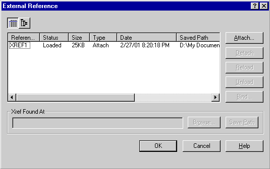
Attaches, overlays, lists, binds, detaches, reloads, unloads, renames, and modifies paths to external references (xrefs) in the current (or host) drawing.

Dialog Box Options
  • List of external references (List View and Tree View)
  • Attach (displays the Attach Xref dialog box)
  • Detach
  • Reload
  • Unload
  • Bind (displays the Bind Xrefs dialog box)
  • Browse
  • Save Path

List of External References

List View

Displays a flat listing of the attached xrefs and their associated data. You can sort the list of references by name, status, type, file date, file size, or the saved path and file name.

Selecting any field highlights the xref name and selects the xref.

  • Reference Name. Lists the names of the xrefs as stored in the block definition symbol table.
  • Status. Shows whether the xref is loaded, unloaded, unreferenced, not found, unresolved, orphaned, or marked for unloading or reloading.
  • Size. Shows the file size of the corresponding reference drawing. The size is not displayed if the xref is unloaded, not found, or unresolved.
  • Type. Indicates whether the xref is an attachment or an overlay.
  • Date. Displays the last date the associated drawing was modified. This date is not displayed if the xref is unloaded, not found, or unresolved.
  • Saved Path. Shows the saved path of the associated xref (this is not necessarily where the xref is found).

Tree View: Displays a hierarchical representation of the xrefs, displaying the relationships between xref definitions. Tree view shows the level of nesting relationship of the attached xrefs, whether they are attached or overlaid, and whether they are loaded, unloaded, marked for reload or unload, or not found, unresolved, or unreferenced.

You can also use the F3 and F4 keys to toggle between list view and tree view.

Attach: Displays the Attach Xref dialog box or the Select File to Attach dialog box.

Detach: Detaches one or more xrefs from your drawing, erasing all instances of a specified xref and marking the xref definition for deletion from the symbol table. Only the xrefs attached or overlaid directly to the current drawing can be detached; nested xrefs cannot be detached. AutoCAD LT cannot detach an xref referenced by another xref or block.

Reload: Marks one or more xrefs for reloading. This option rereads and displays the most recently saved version of the drawing.

Unload: Unloads one or more xrefs. Unloaded xrefs can be easily reloaded. Unlike detach, unloading does not remove the xref permanently. It merely suppresses the display and regeneration of the xref definition, to help current session editing and improvement of performance.

Bind: Displays the Bind Xrefs dialog box.

Browse: Displays the Select New Path dialog box, in which you can select a different path or file name.

Save Path: Saves the path, as it appears in the Xref Found At field, to the currently selected xref.


Attribute Definitions

An attribute is informational text associated with a block. An attribute definition specifies an attribute's properties and which prompts appear when the block is inserted.

After you complete the Attribute Definition dialog box, the attribute tag appears in the drawing. AutoCAD erases the attribute tag from the drawing when the attribute tag is included in a block definition using the BMAKE or BLOCK command. When you insert the block, AutoCAD displays the attribute value at the same location in the block with the same text style and alignment.

Attribute Definition Dialog Box

Mode

Sets options for attribute values associated with a block when you insert the block in a drawing.

These options are stored in the AFLAGS system variable.

  • Invisible. Makes the attribute value invisible. The attribute value is not displayed or printed. To display invisible attributes, use the ATTDISP command.
  • Constant. Assigns a fixed attribute value. The attribute value is inserted automatically into the drawing when the block is inserted.
  • Verify. Instructs AutoCAD LT to prompt you to verify that the attribute value is correct before the block is inserted in the drawing.
  • Preset. Sets the attribute to its default value when you insert a block containing a preset attribute.
Attribute

Sets attribute data.

  • Tag. Identifies each occurrence of an attribute in the drawing. Enter the attribute tag using any combination of characters, except spaces.
  • Prompt. Enter the prompt that you want displayed when you insert the block containing this attribute definition. If you do not enter a prompt, the attribute tag is used as a prompt. To create a leading blank for the value, start the text string with a backslash (\). To use a backslash as the first character, enter two backslashes.

    Note: This text box is unavailable if you select Constant in the Mode area.


  • Value. Enter the default attribute value (maximum of 256 characters). To create a leading blank for the value, start the text string with a backslash (\). To use a backslash as the first character, enter two backslashes.
Insertion Point

Specifies the location of the attribute when the block is inserted in a drawing. Select a point in the drawing or enter X, Y, and Z coordinate values.

  • Pick Point. Choose Pick Point to close the dialog box so that you can select an insertion point with the mouse. After you select a point, the dialog box is redisplayed.
  • X. Enter the X value for the insertion point.
  • Y. Enter the Y value for the insertion point.
  • Z. Enter the Z value for the insertion point.
Text Options

Sets the justification, style, height, and rotation of the attribute text.

  • Justification. Select the justification for the attribute text.
  • Text Style. Select the text style for the attribute text. Currently loaded text styles are displayed. To load or create a text style, see STYLE.
  • Height. Enter a value for the height of the attribute text. Alternatively, choose Height to specify a height with your pointing device. The height is measured from the origin to the location you pick using your pointing device. After you specify a height, the dialog box is redisplayed.

    Note: The Height and Rotation options are not available for all justification settings.

  • Rotation. Enter a value for the rotation angle of the attribute text. Alternatively, choose Rotation to specify a rotation angle with your pointing device. The rotation angle is measured from the origin to the location you pick using your pointing device. After you specify a rotation, the dialog box is redisplayed.

    To specify a rotation angle on the screen, choose Rotation. The rotation angle is measured from the origin to the location of the cursor when you push the mouse button.

Align Below Previous Attribute

Select to place the attribute tag directly below the latest defined attribute.

Note: If you have not previously defined an attribute definition, this check box is unavailable.

Extracting Information from a Drawing's Blocks

Attribute Extraction Dialog Box

File Format

Select the file format for the attribute data extracted from the current drawing.

  • Comma Delimited File (CDF). Generates a file containing one record for each block reference. Character fields are enclosed in single quotation marks and separated by commas.
  • Space Delimited File (SDF). Generates a file containing one record for each block reference. Character fields of each record have a fixed width. Field separators are not used.
  • Drawing Interchange File (DXF). Produces a subset of the drawing interchange file format containing only block reference, attribute, and end-of-sequence objects. No attribute template file is required. The output file has a .dxx extension to distinguish it from normal DXF files.
Select Objects

Selects objects from which to extract attribute data. When you have finished selecting objects, the Attribute Extraction dialog box is redisplayed.

Attribute Template File

Specifies the file to use as a template for the output extract file in CDF and SDF formats. Enter the path and file name to use, or choose Attribute Template File to display the Attribute Template File dialog box.

Format must be as follows:

fieldname     Nwwwddd        (for numeric values with decimal allowances)

fieldname     Nwww000        (for numeric values without decimal allowance

fieldname     Cwww000        (for character values)


(The N or C denotes "number" or "character".  The "www" represents the number of spaces of data you wish to occupy in the output file.  If the longest value in your field is 20 characters long, you would replace the "www" with "020".  If you want to have decimals recorded to two significant figures, replace the "ddd" with "002")


For Example:  If the fieldnames (attribute tags) of a tree block were "number" "species" and "size", I might make a template file with Notepad as follows:


Note: If you selected Drawing Interchange File in File Format, Attribute Template File is unavailable.

Output File

Specifies the file name and location for the extracted attribute data. Enter the path and file name for the extracted attribute data, or choose Output File to display the Output File dialog box.

Many database and spreadsheet programs can work with the data generated by the output file.  Excel can import the data by using the "Get External Data" feature on the Data menu.


Assignment: Exercise 2, due at beginning of class, Week 5

Syllabus