5 Modeling 2
Objectives:
- To understand the similar basis but different implementation of common 3D modelers
I. Many choices, what criteria?
- Ease of use vs. power
- Current practice vs. future practice
- General vs. Architectural
- Phase of use: Conceptual vs. Development vs. Documentation, Manufacturing
Categories:
- quick sketch
- architectural 2D/3D
- high-end visualization i.e. for animation
II. Criteria
ORGANIZATION: What are the basic parts of a modeling software? How does the definition of elements, operations and organizing structures (layers, nested objects, symbols) affect what it can do?
INTERFACE: How do the selection and command processes foster efficient work? What could be improved?
CONTEXT: Does it run on both PC's and Mac's? Who is using it already? What support is available?
FUNCTIONALITY: What do I need to do? What forms and what tolerances do I need?
|
Convention
|
FormZ
|
Revit, ArchiCad & Vectorworks
|
Others
|
| Geometric Primitives (basic forms) | Objects are either 2D drafting elements, surface solids or 3D solids.
Special objects such as surface meshes and metaballs have different behaviors |
Objects are defined as architectural components with specific properties | Maya, Rhino and other advanced modellers are based on NURBS (Non-uniform Relational B-Splines) or NURMS that allow organic modeling. |
| Operations | All modelers have 2D to 3D operations of extrusion, revolve, lofting,
and geometric transformations (move, scale, rotate, mirror). |
||
| Editing | Points, segments and faces as well as objects can be manipulated (i.e. topological levels) | Object manipulation depends on kind of object | Flexible editing of points, segments, faces, etc. In MAX, Object oriented stacks of transformations can applied to different objects. Steps in the transformation chain can be removed. |
| 2D & 3D worlds | Information for 2D & 3D are separated, but stored in same file | 2D drawings are views of 3D model | Layers can have either 2D or 3D information in the same space. Entities are either 2D elements, 3D surfaces or 3D solids. Not both |
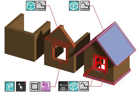
| Drafting | Simple "Draft" tools are not optimized for architectural conventions. | Wall editing tools, insertable windows and doors speed up drafting & enforce architectural conventions | General modeler/renderers (Maya, Lightwave, Rhino, Alias) don't worry about drafting. Mechanical tools do have 2D/3D capability with parametric dimensioning. |
| Construction Planes | System defined planes are supplemented by user defined planes | Horizontal floor and roof planes are set with elevation levels | AutoCad has xyz World Coordinate System (WCS), User Coordinate Systems (UCS) |
| Layers | All but the most primitive modeling programs have some sort of layering system. | Programs like Microstation store information in separate files which are combined as needed for composite drawings. | |
| Symbols | Limited architectural libraries | Extensive architectural libraries | Non-architectural: many kinds of models available, especially for 3DS MAX |
| Collaboration support | Not supported | Worksets | AutoCad has sharable World blocks (symbols) and underlayable Reference files that can be viewed but not changed. Other programs allow individuals to "check out" sheets of a project. |
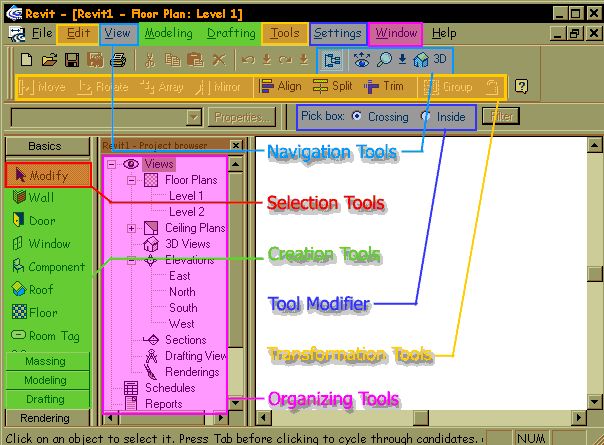
IV. Comparison of Interfaces
V. Exercise:
Working with one or two partners, compare the steps needed to create the following elements: walls, roofs, windows, doors, columns, cornice trim.