Appendix A3: MGL0910 R/V Marcus G Langseth Airgun Arrays |
| MGL0910 Airgun Operations The R/V Langseth airgun array consists of 36 air guns with a total volume of 6600 in3 at 2000 psi. To enhance power and low frequencies for the undershoot lines (longer ranges) the airguns were run at depths of 15 m. For the shorter lines (the crustal and hydrothermal grids) the airguns were run at 9 m, which provides the cleanest source signature. The undershoot lines were also reshot at the same shot points with the airguns at 9m depth. This data will allow us to compare source performance at these two towing depths and to stack the data to improve the signal to noise. The R/V Langseth seismic source consists of four identical linear arrays, or strings each of which has ten air guns. Nine air guns were fired simultaneously, while the tenth was kept in reserve as a spare to be turned on in case of the failure of another air gun. Typically, on each string gun 5 is kept as a spare, but if there were issues with one of the other guns, gun 5 on the string in question was put in service and the other gun was shut off. Seven different volumes of Bolt Models 1500LL & 1900LLXT Long Life Air Guns are used. Guns 1 & 2 are 360 in3 and are used in parallel. Gun 3 is 40 in3. Guns 4 & 5 are 180 in3 and are used in parallel. Gun 6 is 90 in3. Gun 7 is 120 in3. Gun 8 is 60 in3. Guns 9 & 10 are 220 in3 and are used in parallel. 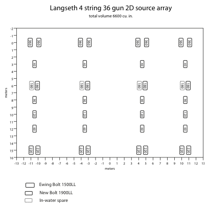 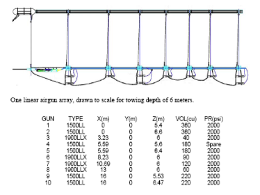 Figure 1: Schematic R/V Langseth gun array layout. The array comprises four identical but separately towed strings, each with ten air guns. (a) Each string is made up of three two-gun clusters and four individual guns. The purpose of the clusters is to provide a larger, more slowly reverberating residual air bubble (which improves overall array tuning) while at the same time reducing the amplitude of that bubble’s reverberation, which further improves tuning. One of the 180 in3 air guns within the central cluster is normally turned off and held in reserve as a spare. (b) Detailed side view of the towing arrangement for one of the four identical source strings on the R/V Langseth, drawn to scale for a towing depth of 6 meters. The airgun array signature depends on the towing depth. 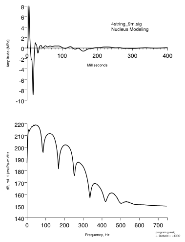 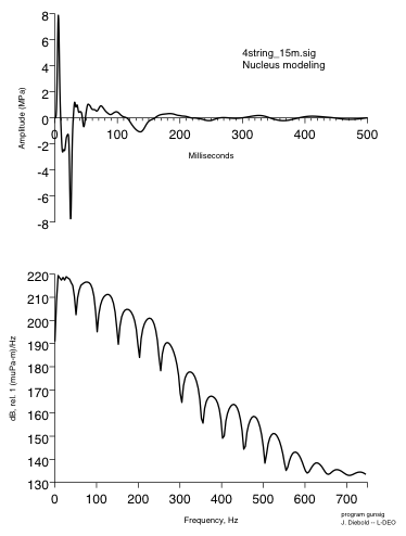 Figure 2: Airgun signature modeled for 9 and 15-m tow depths by John Diebold – LDEO using gunsig. 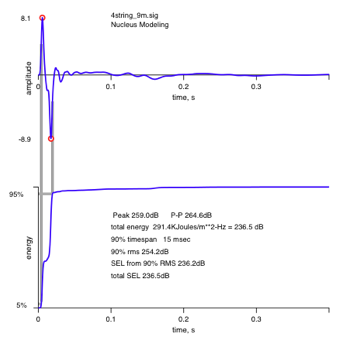 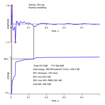 Figure 3: Airgun array source metrics for 9 and 15-m tow depths modeled by John Diebold - LDEO The rate at which sound levels decay around the airgun source depends on the towing depths. Acoustic received levels were quantified using sound exposure level (SEL) calculations. In the U.S.A. the current standard for mitigation is root-mean-square (RMS). The RMS amplitude, typically expressed as dB referenced to 1 mPa, is a measure of the average pressure over the duration of the pulse. It is calculated as the square root of the sum of the squared pressures within a given time window and therefore depends on the selection of this window and its duration. SEL is a measure of the energy flux density of an arrival, defined as the product of signal intensity and duration. Its decibel value (dB referenced to 1 Pa2s) will equal the RMS decibel amplitude if calculated for a 1 s duration window: SEL(dB) = RMS(dB) + 10 log10 (T), where T is the RMS integration time in seconds. For signals with durations <1 s, as expected for an air gun pulse, the SEL value will be less than the RMS. Current practice is to use 170 dB SEL as a proxy for 180 dB for the RMS sound exposure level used in permitting. F 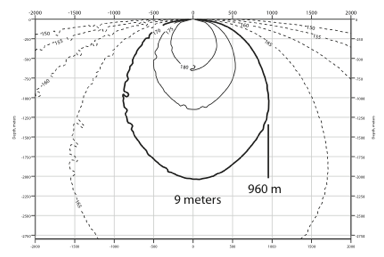 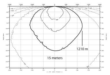 igure 4: Decibel sound level for the airgun source towed at 9 and 15 m. The contours are SEL (sound exposure level), which is similar to EFD (energy flux density) and RMS sound exposure level with a fixed 1-second integration window. igure 4: Decibel sound level for the airgun source towed at 9 and 15 m. The contours are SEL (sound exposure level), which is similar to EFD (energy flux density) and RMS sound exposure level with a fixed 1-second integration window. |
|||||
| Two airgun tow depths were used during the survey: 15m and 9m. The 15m tow depth was used at the start of the survey to increase the low frequency content of the signal. The 9m tow depth was used for the remainder of the survey to provide the cleanest source signal. * Shot at 15m gun depth: Lines 2, 2R, 3, 3R, 4, 5, 37, 38 (Sequence 1 through 8) * Shot at 9m gun depth: Lines 1, 2A, 5A, 6, 7 through 35, 39 & 40 (Sequence 9 through 45) |
|||||
| RV Langseth Sensor configration is described in Appendix A9: MGL0910 RV Langseth Sensor Configuration and Data Formats |
|||||
|
|||||||
|
|||||||