|
|
|
|
Appendix A2: MGL0910 Seismic Survey Summary
|
|
|
|
|
 | Included in this appendix are the following:
|
|
|
|
|
|
 | Description of the Survey.
|
|
|
|
|
|
| Seismic line naming convention
|
|
|
|
|
|
| Shot log file description
|
|
|
|
|
|
| Maps of the seismic survey
|
|
|
|
|
|
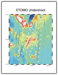
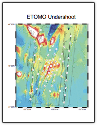
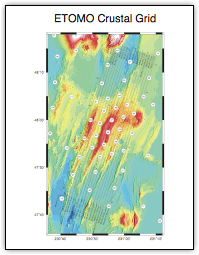
| The ETOMO seismic survey provides multi-scale imaging of the Endeavour segment. The 3 primary shooting plans are referred to as: (i) Undershoot, (ii) Crustal grid, and (iii) Hydrothermal grid.
While all data will contribute information on crustal and mantle structure beneath the Endeavour segment, broadly speaking the 3 shooting plans provide constraints as follows:
|
|
|
|
|
|
| Undershoot: Shallow mantle structure beneath the entire ridge segment.
|
|
|
|
|
|
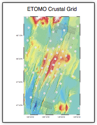
| Crustal grid: Three-dimensional structure of the crust along the ridge axis, including the axial magmatic system.
|
|
|
|
|
|
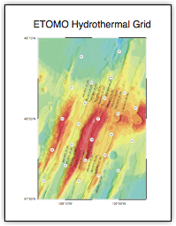
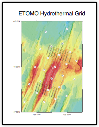
| Hydrothermal grid: Detailed, three-dimensional structure of the magmatic-hydrothermal reaction zone above the segment-centered AMC.
|
|
|
|
|
|
| Two airgun tow depths were used during the survey: 15m and 9m. The 15m tow depth was used at the start of the survey to increase the low frequency content of the signal. The 9m tow depth was used for the remainder of the survey to provide the cleanest source signal.
* Shot at 15m gun depth: Lines 2, 2R, 3, 3R, 4, 5, 37, 38 (Sequence 1 through 8)
* Shot at 9m gun depth: Lines 1, 2A, 5A, 6, 7 through 35, 39 & 40 (Sequence 9 through 45)
|
|
|
|
|
|
| Seismic line naming convention:
|
|
|
|
|
|
| All shooting was done along lines and each line is given a Line Name and a Sequence Number, as defined below. All shooting was on position and each shot is given a unique Shot Number, also defined below. To achieve a desired shot interval, the ship speed was adjusted; a useful rule of thumb is that 4 Kts is 2 m/s.
|
|
|
|
|
|
| The convention for naming survey lines is: MGL0910_##[A/R] (%%), where:
|
|
|
|
|
|
| Line Name is encoded in MGL0910_##[A/R]. Line names vary between MGL0910_01 to MGL0910_40. These numbers are arranged geographically from east to west for each shooting plan, except for lines of opportunity.
|
|
|
|
|
|
| The letters in brackets [A/R] are optional. The first time a line is shot, the line name does not include an A or an R. If a line is reshot with the same source configuration an ‘R’ appears after ##, indicating ‘Reshoot’. If a line is reshot with a different source configuration (e.g., tow depth), an ‘A’ is appended after the line number.
|
|
|
|
|
|
| For example, there are 3 seismic surveys along MGL0910_02:
|
|
|
|
|
|
| MGL0910_02 (07). First time line is shot, tow depth of 15 m.
|
|
|
|
|
|
| MGL0910_02R (08). Reshoot of line due to premature end of sequence 07; tow depth of 15 m.
|
|
|
|
|
|
| MGL0910_02A (39). Shooting the line with a different tow depth (9 m).
|
|
|
|
|
|
| Note: Note that there is no line MGL0910_36. The original design had line numbers going from 1 to 35 (the last ones are in the hydrothermal grid). Then when we added extra lines during the cruise they started at line number 37 (There are shown on the undershoot map). Line 36 was skipped.
|
|
|
|
|
|
| Sequence number is unique and encoded in parentheses (%%). Sequence numbers vary between 01 and 45. In the example given above, sequence numbers 07, 08 and 39 were all shot along MGL01910_02. The sequence number is assigned consequetively in the order in which the lines were shot.
|
|
|
|
|
|
| Shot Number is a unique six digit number (e.g., 0041125).
|
|
|
|
|
|
| The first two digits are always zero.
|
|
|
|
|
|
| The third and fourth digits refer to sequence number.
|
|
|
|
|
|
| The fifth to seventh digits refer to shot number.
|
|
|
|
|
|
| Shot numbers increment from south to north, with the first planned shot along sequence ## being 00##021 if that sequence is either an undershoot or crustal grid line. For the hydrothermal grid, the first planned shot along these lines begins with number 065; this was done so that shot numbers for the hydrothermal and crustal grids are geographically consistent. Due to run-in, the first shot number may be less than 21 for some lines.
|
|
|
|
|
|
| All lines were shot through the end point. During turns the guns went on an internal cycle with a rep-rate of ~20 s.
|
|
|
|
|
|
| Shot log file description:
|
|
|
|
|
|
| For each line in the seismic survey there is a shot log. These log files are named according to the convention: MBL0910_###.obsip. Where ### is the seismic line number followed by a letter (A or R) as necessary. This naming convention is described in Appendix A2: MGL0910 Seismic Survey Summary.
|
|
|
|
 |
|
|
| WHOI provided the following description of the OBSIPshotFile
|
|
|
|
|
|
|
| Endv_UndershootGrid_report_activesourcelines_bth.pdf
|
|
|
|
|
|
|
| Endv_UndershootGrid_shoot_bth_2.pdf
|
|
|
|
|
|
|
| Endv_CrustalGrid_report_activesourcelines_bth_3.pdf
|
|
|
|
|
|
|
| Endv_CrustalGrid_report_shoot_bth_3.pdf
|
|
|
|
|
|
|
| Endv_HydroGrid_report_activesourcelines_bth.pdf
|
|
|
|
|
|
|
| Endv_HydroGrid_report_shoot_bth_2.pdf
|
|
|
|
|