J. J. Donovan, Practical Considerations for Mosaic Imaging, Scanning 97 Conference Proceedings, Monterey, CA, April, 1997.
John J. Donovan
Department of Geology and Geophysics
University of California
Berkeley, Ca, 94720-4767
Digital imaging in the electron microprobe and scanning electron microscope has recently progressed to the point where new and exciting capabilities, once thought to be impractical, can now be realized. One of these capabilities is the automatic creation of digital mosaic images. That is, the ability to construct a single large image from a set of multiple sub-images, by placing the sub-images together, either adjacent to each other or overlapping. This discussion will be limited to mosaic imaging where both the beam and the stage are scanned so that large sample areas can be both efficiently and accurately imaged.
The ability to perform mosaic imaging can be applied to problems involving low to ultra-low magnification imaging (< 100-1X), especially when wavelength dispersive spectrometers (WDS), with their associated Bragg defocusing properties, are utilized as a signal source. So that the mosaic imaging process be made as automatic as possible, both the software developer and the operator are required to carefully consider two factors each relating to the software and hardware of the electron beam instrument.
The most fundamental image property for accurate mosaic imaging, from the software developer point of view, is the creation of images that are registered precisely to the instrument stage coordinates. For mechanical stages that use the same units of length in both x and y, a simple two point image registration may be applied, usually on any two diagonal corners of the image. Images that are non-rectilinear (acquired using a tilted stage for example), require a more complex four point trapezoidal transformation. The usefulness of a coordinate registered image is that the aspect ratio of the image is always correctly displayed, regardless of the actual pixel resolution within the image. This means that the image pixels are rectangular in shape, with the actual aspect ratio depending on the image area extent and the pixel resolutions involved. The image registration in stage coordinates or microns should be automatically saved to the image file as a private TIFF tag. Similarly, it is also appropriate to save the image gray or color level values in stage or sample coordinates as a separate registration field. For example, analog images registered in volts, x-ray images in counts and quantitative images in weight percent.
Successful mosaic imaging requires careful registration of the image in stage coordinates, which means that the beam scan must be precisely calibrated with respect to the stage motion. Often, a separate calibration in both the x and y directions of the beam scan is necessary, especially for scan coils with unequal response characteristics. To be acceptable to the eye, mosaic images usually require that this calibration be performed with an accuracy of better than 1%.
Stage reproducibility is also critical when the stage motion is of a magnitude similar to the degree of mechanical backlash. However, the use of a stage backlash correction can reduce this source of error significantly for those stages that do not use optically encoded positioning.
The second consideration for successful mosaic imaging, is the calibration of the scan rotation. All beam scan images are rotated due to the charge of the electron and the magnetic fields of the microscope lenses. Under favorable conditions, the eye can discern scan rotation defects in a mosaic image of less than 0.5 degrees. Therefore considerable effort is required by the operator to carefully adjust the scan rotation, to ensure that the vertical and horizontal features on the beam scan image are close to parallel with respect to the stage motion. However, the operator must be aware, that because the electron beam path length changes slightly as the operating voltage, focus and magnification are varied, it will be necessary to carefully check the scan rotation calibration as the instrument conditions are modified before quality mosaic images can be obtained. Although all electron beam instruments have built in rotation compensation for most adjustments, it is likely that some small errors will remain even with the best electron optic systems. The acquisition of a few test mosaic images on a diagonal grid is quite useful for this purpose.

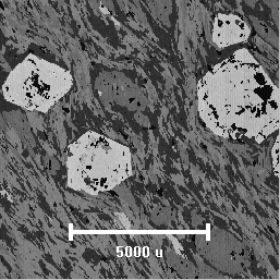
Fig. 1- A large area WDS Mg Ka x-ray mosaic image acquired using both beam and stage scanning over an area of 10 by 10 mm. The beam scan magnification was 1000X, which required a mosaic of over 100 by 100 sub-images. Pixel resolution was 512 by 512 at 0.2 seconds counting time per pixel yielding approximately 14 hours of acquisition time.
Back To Department of Earth and Planetary Science Home Page