Chapter 25: Electromagnetic Inductance

We have just seen that varying charge densities, current flows, I lead to magnetic fields B; a remarkable discovery in the 1800s was that voltages, and hence current flows, could be induced in a wire if the magnetic field B through a wire loop was varied. The phenomenon of inducing voltage is known as Electromagnetic Induction.

Voltage can be induced either by moving the magnet or moving the loop. The voltage produced depends on:

  • The number of loops involved
  • The area covered by the loops involved
  • The speed on which the change occurs

We have:
  • More loops means more higher induced voltage
  • The larger the area means more field enclosed and so the higher the voltage
  • The faster the changes are made, the greater is the induced voltage.

The sense in which the field changes in the loop determines the direction in which the current flows (see the bottom picture on the right). Inserting and withdrawing the coil (as shown) produces driving voltages which push in different directions; this leads to an alternating current (AC).

Remarkably, it doesn't matter whether the magnet moves or the wire coil moves, the effects are the same.

Faraday's Law

    The induced voltage in a coil is proportional to the product of its number of loops, the cross-sectional area of each loop, and the rate at which the magnetic field changes within those loops.

There is a caveat to Faraday's Law in that once you induce a voltage, the voltage leads to a current. Nature tries to oppose rapid changes and the induced current produces a magnetic field which tries to cancel out the effect of the changing field, it softens the effect of the varying field.


Generators and Motors

Recall that motors convert electrical energy into kinetic energy (mechanical energy). Generators operate on the same physics principles but they take mechanical energy and turn it into electrical energy.

  • The unipolar inductor on the top right shows a spinning conducting wheel; someone or something is turning its handle (inputing mechanical energy to the system) causing it to spin. The spinning disk is embedded in the magnetic field produced by the magnet. The spinning wires lead to current flow. The current always flows in the same direction leading to direct current (DC). Q: In which direction does the current flow?

  • In the middle panel, we see a hydroelectric plant . The dam (2) holds back the water flowing in a river (in the reservoir, 1). The water is allowed to flow slowly through the dam to the continuation of the river below where it causes a turbine to spin (at 3. The axle of the spinning turbine causes the coil ( 4) to spin in the magnetic field of the big magnets. This induces an alternating current (AC) in the spinning coil, which is then transmitted to neighboring communities. We consider transmission of power in the next box.
  • In the bottom panel, we see a wind turbine. The wind causes the propeller to spin whose shaft spins a wire cool in a magnetic field generating a voltage. The voltage drives a current. The Step Up transformer (3) increases the voltage for transmission.

Look below at a motor. Note the similarities. The only difference is that the battery causes a current to flow which causes the wire loop to spin.

If we look at one side of the wire loop we see that the current in the one side reverses direction every half-spin ===> AC.


Power Transmission


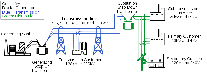
The power is generated at a generating station, such as at a hydroelectric plant, a wind turbine site, nuclear reactor, ... and then must be transported to where it is used. The question is how to do it efficiently.

  • The first step is to generate the power, P = I x V in the circuit. This is accomplished in many ways, some of which have been discussed.
  • Note that there is a step before the actual transmission occurs. The Power (energy) is run through a transformer where the voltage is increased to very high levels, say > 100,000 Volts.

    Q: Why is the voltage increased to these high levels?

    • As the current flows through the transmission line, the friction (resistance) causes it to lose energy (Ohmic Losses). The rate at which energy is lost is given by

      Q = I2 x R

      The larger the current I and/or the larger the resistance R, the more frictional (Ohmic) losses there are. So, to minimize the losses, we want to make either I small or R small (or make both small).

    • So for a fixed amount of power, P = I x V, if we step-up the voltage, V, then less current, I, is needed to carry the energy! A stepped-up voltage, V, lowers the current, I, leading to less Ohmic losses.

  • At the destination, a series of Step Down transformers are used to lower the voltage, e.g., to 110 or 220 Volts for use in homes.

Transformers

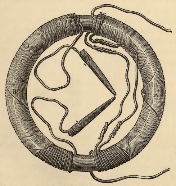
Transformers can be understand based on Faraday's Law. We have that:

  • AC is run through the coil on the left hand side of the transformer. The changing current produces a changing magnetic field B. This changing magnetic field threads the coil on the right inducing a voltage. In this way energy is transported from the left to the right without a connecting wire.
  • The transformer can be made more efficient, however, by adding material into the coils, e.g., ferro-magnetic material. The magnetic field is then enhanced and guided by the ferro-magnetic material to the coil on the right. There, the enhanced varying magnetic field induces a voltage.
  • If each side had the same size coil then no change in voltage would occur
  • The left coil has more loops, however, which means that the magnetic field induces a voltage in the right coil lower than the driving voltage
  • This transformer that has more loops on the left than on the right lowers the voltage, it is a Step Down Transformer