HL-1000 Jib Arm Relay Fault Report
Hardy Lifts HL-1000 (GoLift) · University of Oregon · Jefferson Garman · investigated 10–11 September 2026
Symptom: the jib arm drives up by itself and the up/down buttons have no effect.
Diagnosis: the jib arm is moved by an electric linear actuator, and two relays in the enclosure switch it up and down. One of those relays almost certainly has its contacts welded closed, holding the "up" output on. (§2 gives the meter check that confirms which one.)
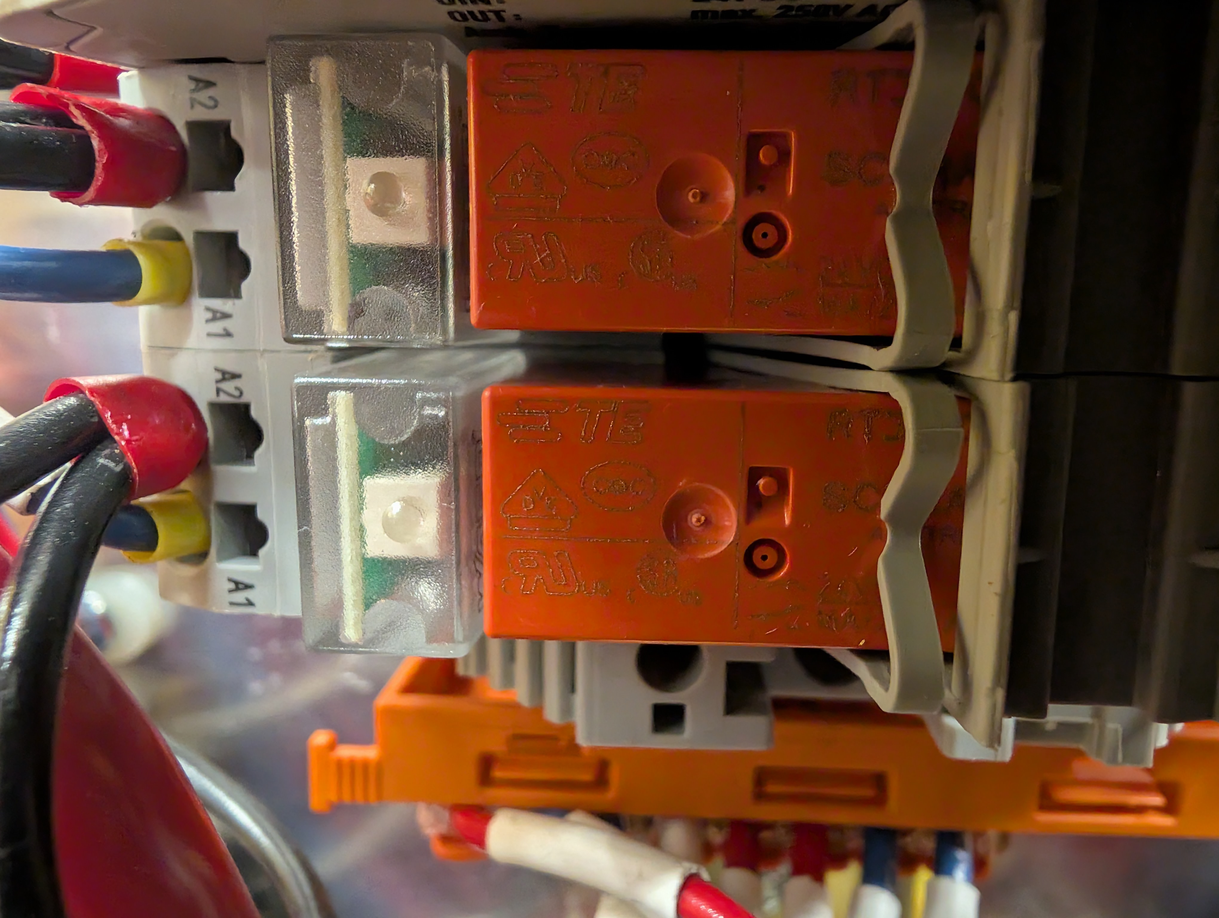
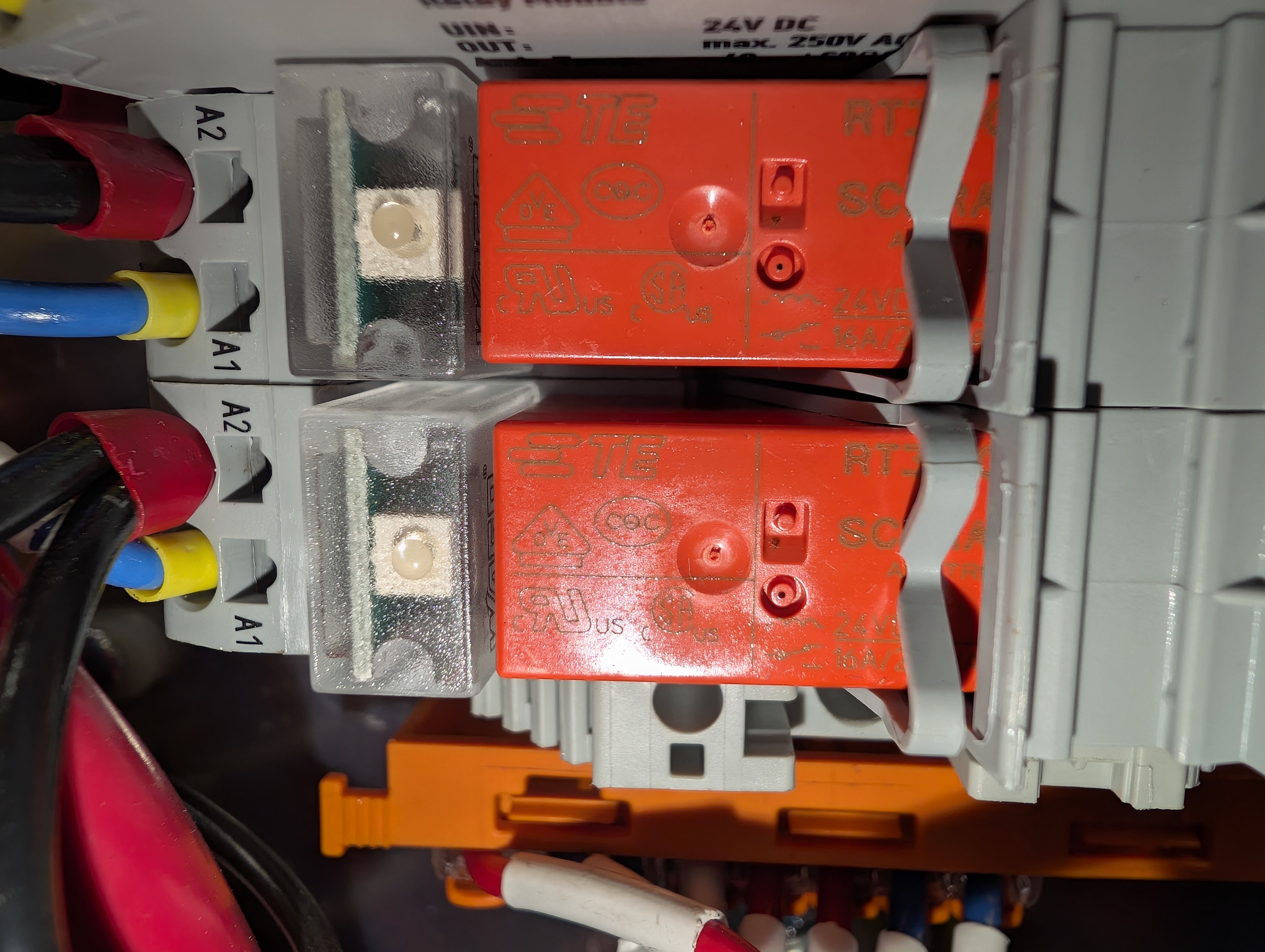
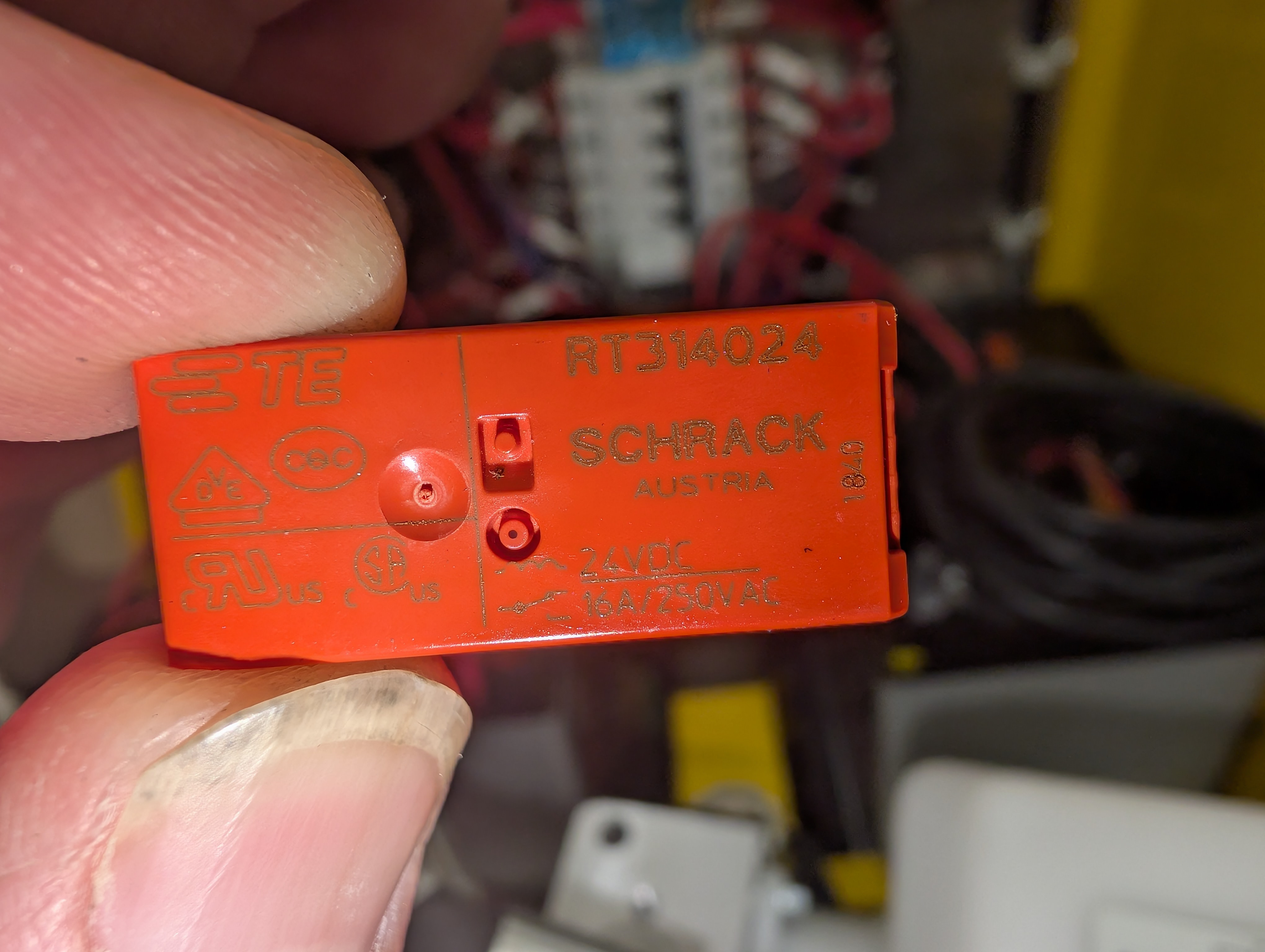
Fix: replace the relays. They are plug-in TE Connectivity / Schrack RT314024 (24 VDC coil, 16 A). Both are identical and eight years old, so replace both.
1. Finding the relays that control the jib arm
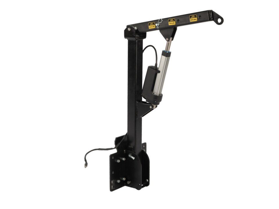
The jib arm is not hydraulic, so the fault had to be somewhere in the electrical path between the control buttons and the actuator. The search followed the actuator cable back into the enclosure:
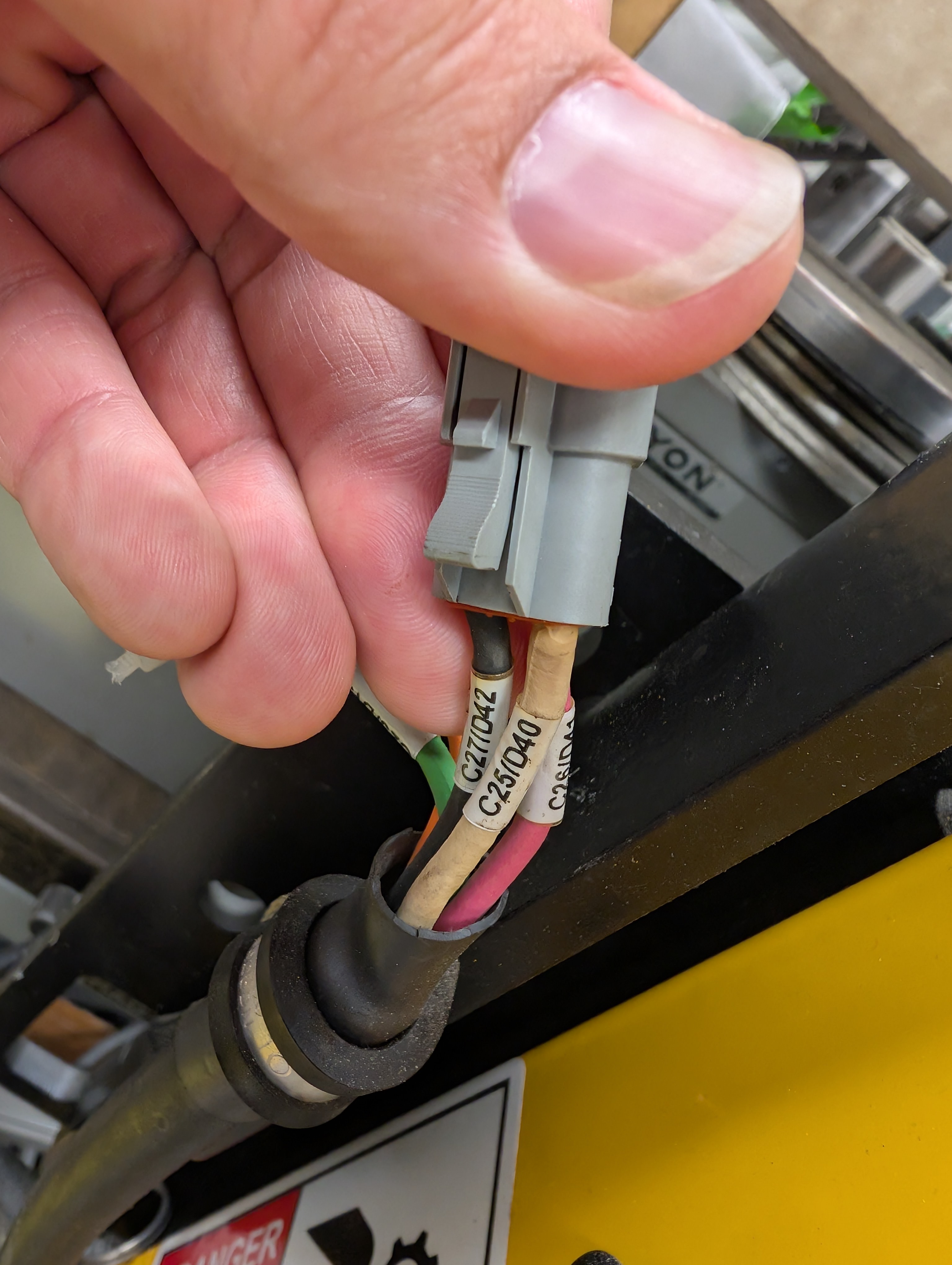
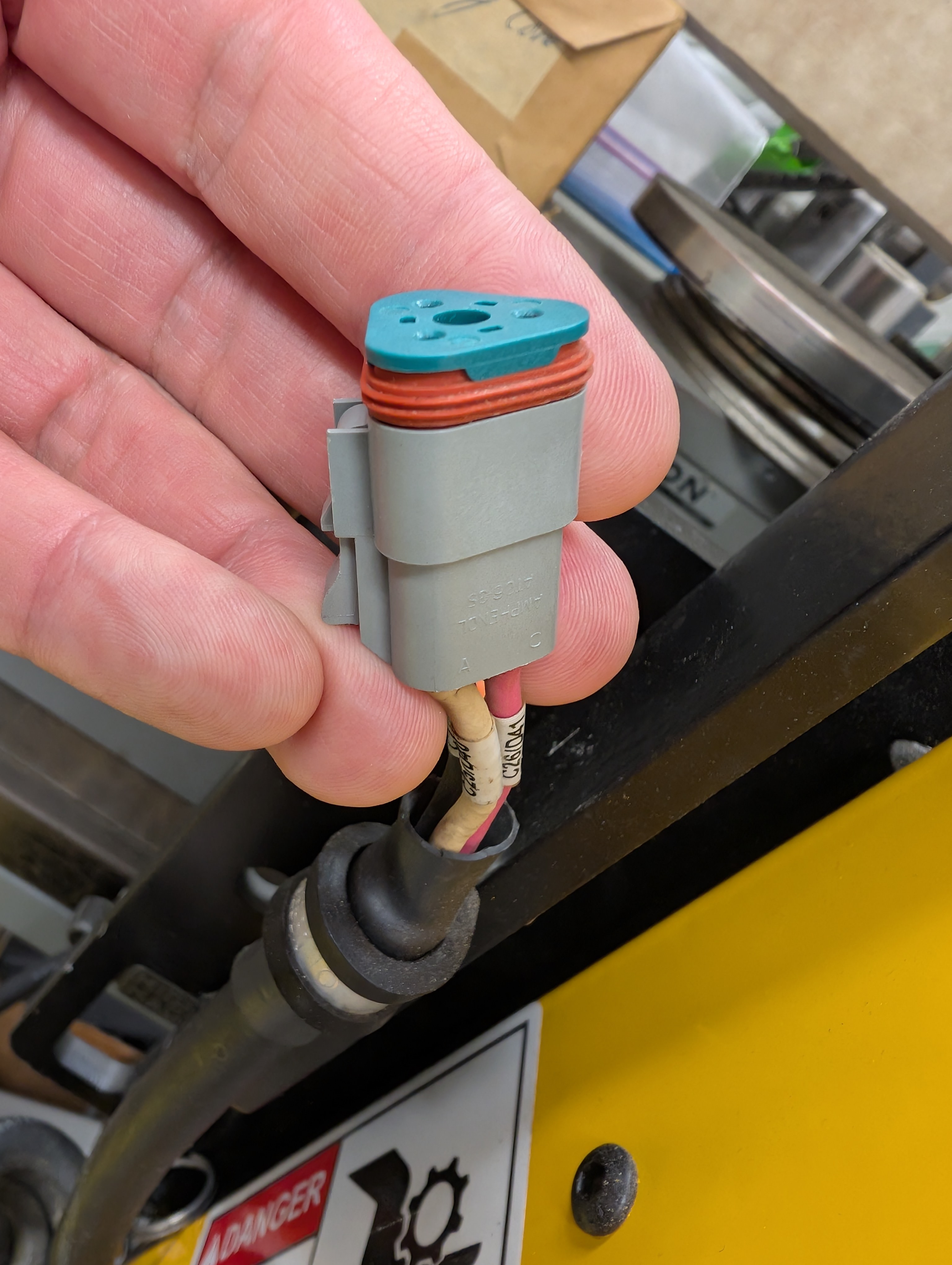
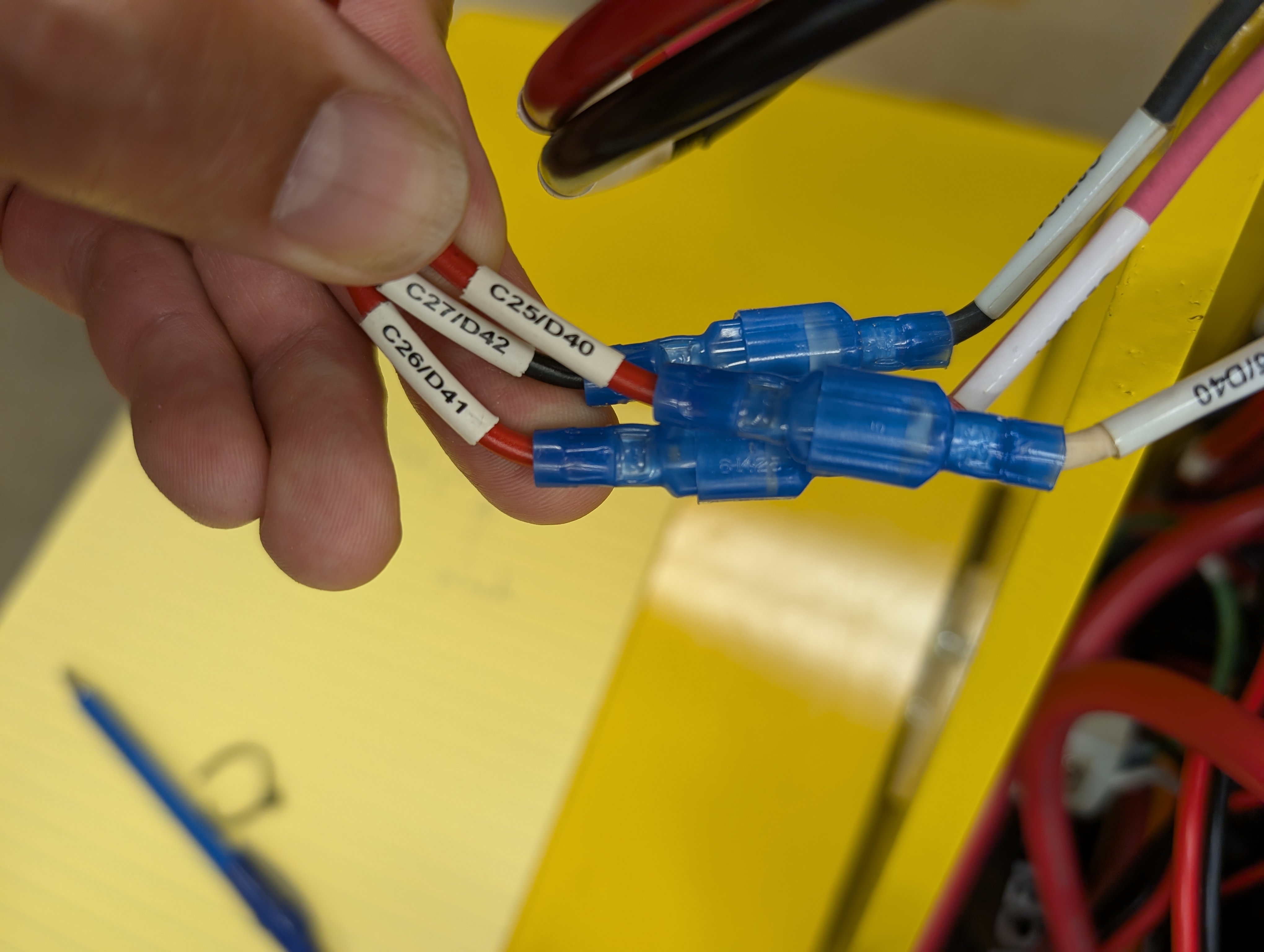
- Outside the enclosure the coiled actuator cable ends at a gray 3-pin Deutsch plug (photos 1–2). Its three conductors are labelled
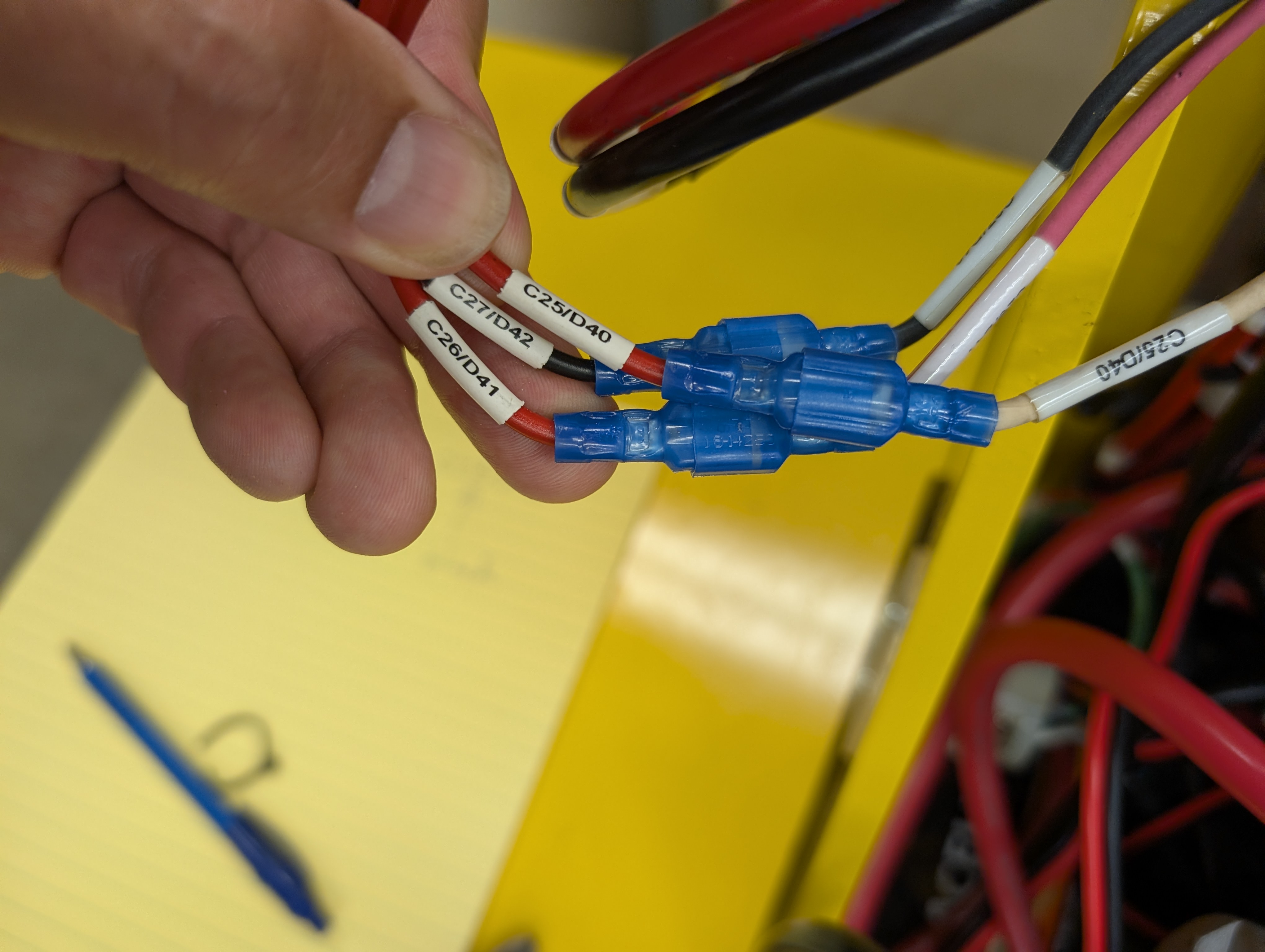
C25/D40(white),C26/D41(red) andC27/D42(black). - Inside the enclosure those three conductors reach blue spade splices (photos 3–4).
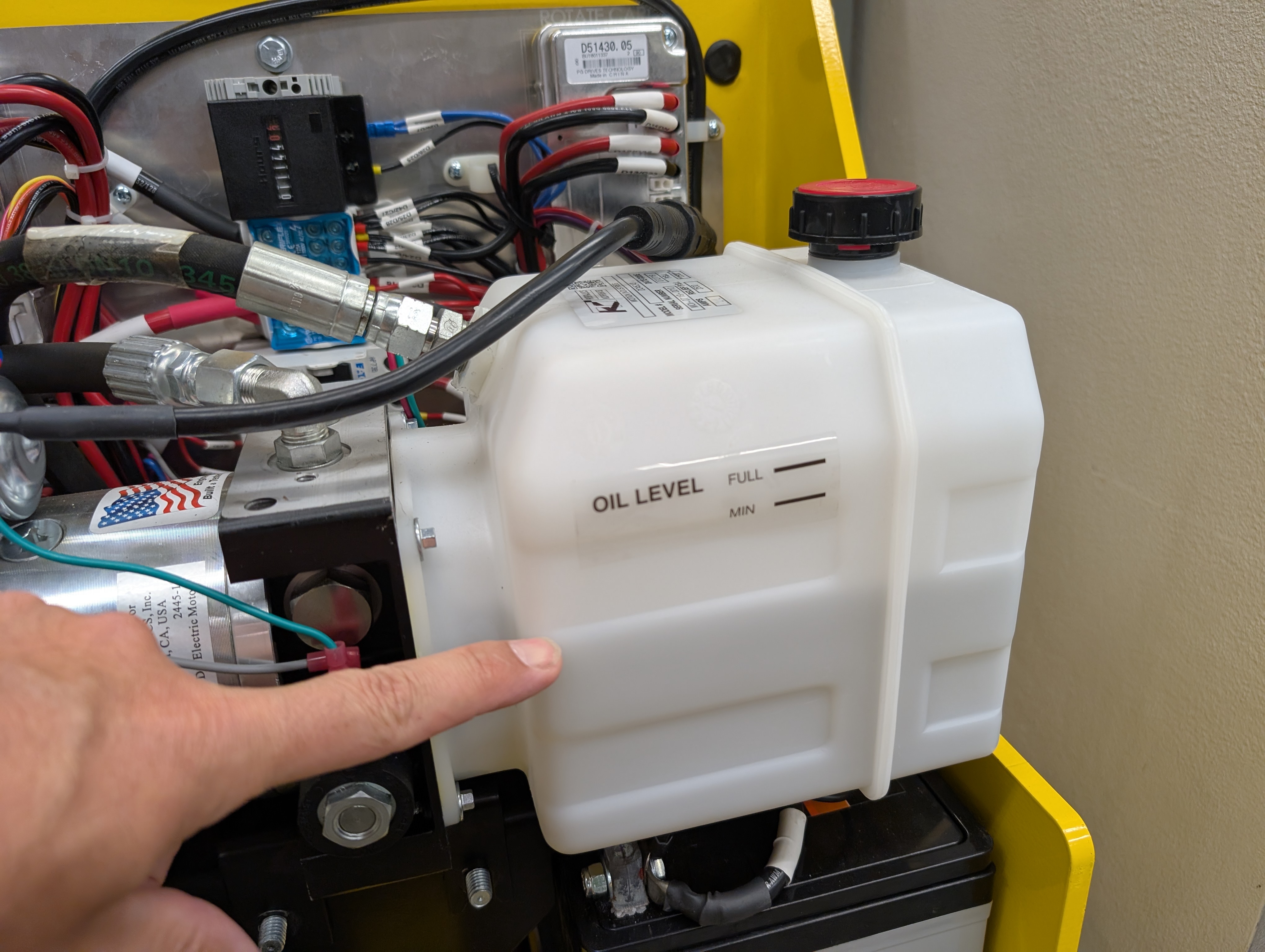
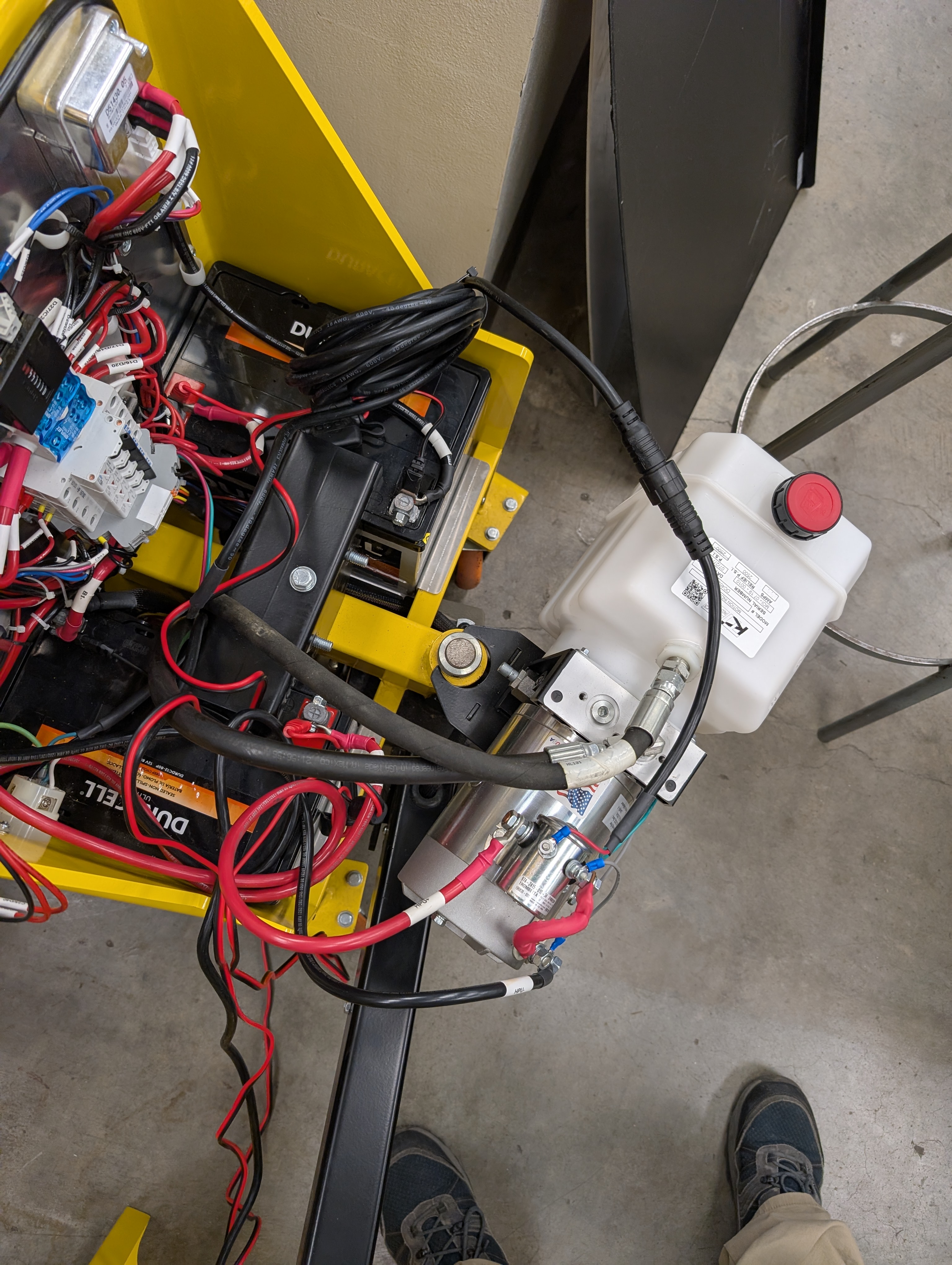
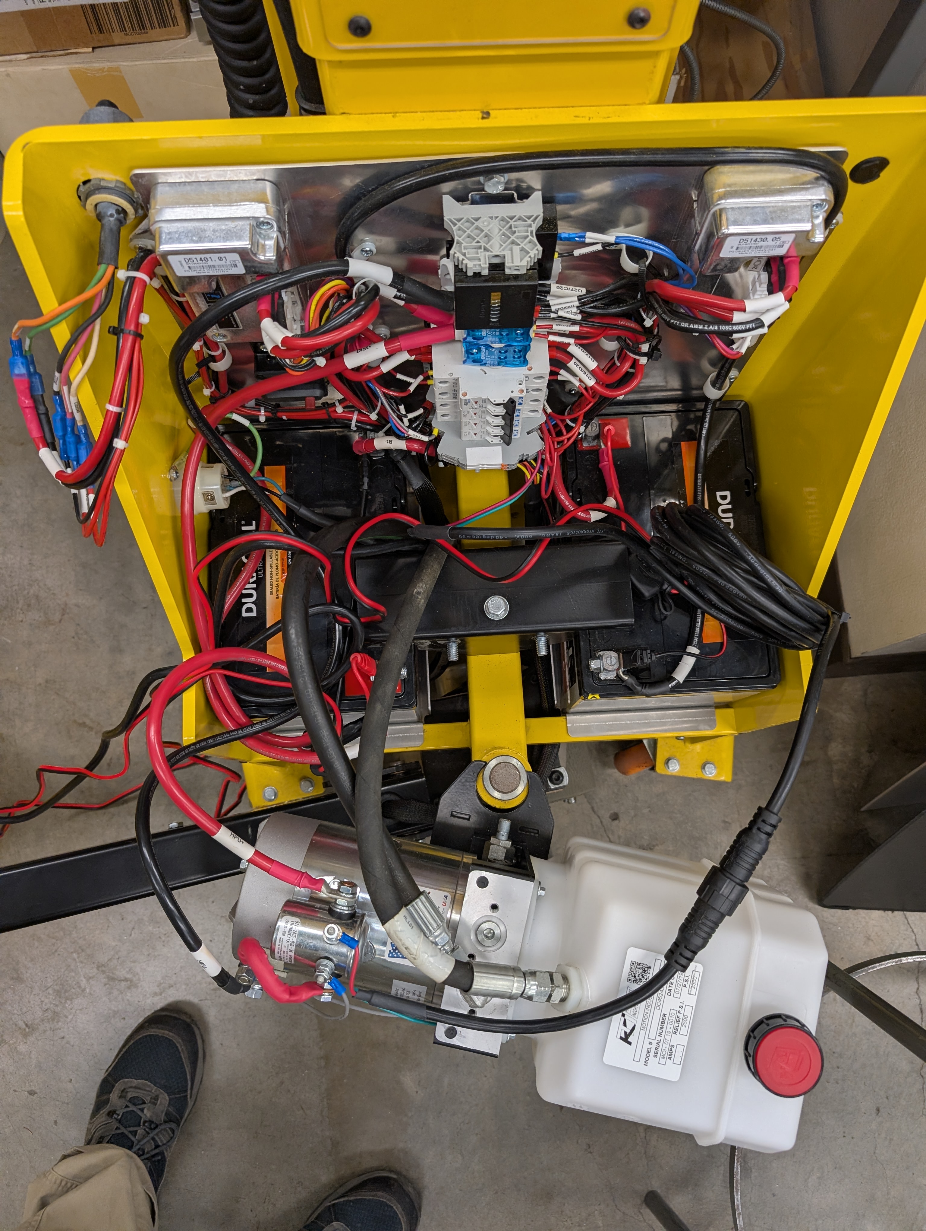
C25/D40andC26/D41both continue on red wire;C27/D42continues on black. - Getting at the DIN rail. The two red wires run to the bottom of the DIN rail, which is hidden behind the mast-lift hydraulic power unit. That unit was unbolted and hung on the control-arm pivot to reach them (photos 6–7). It belongs to the main mast lift and has nothing to do with the jib; while it was out, its reservoir was noticed to be low (photo 5, §4).
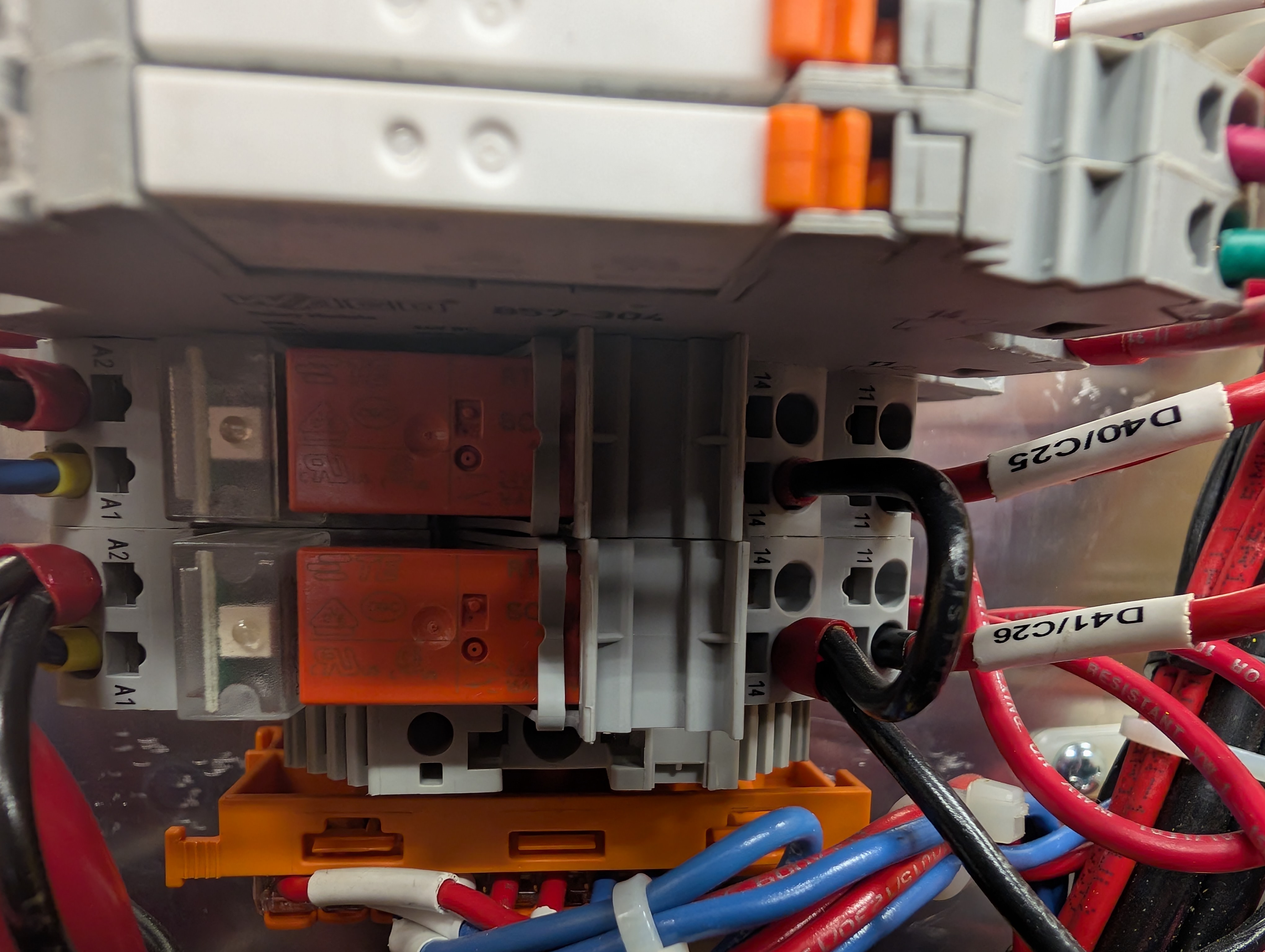
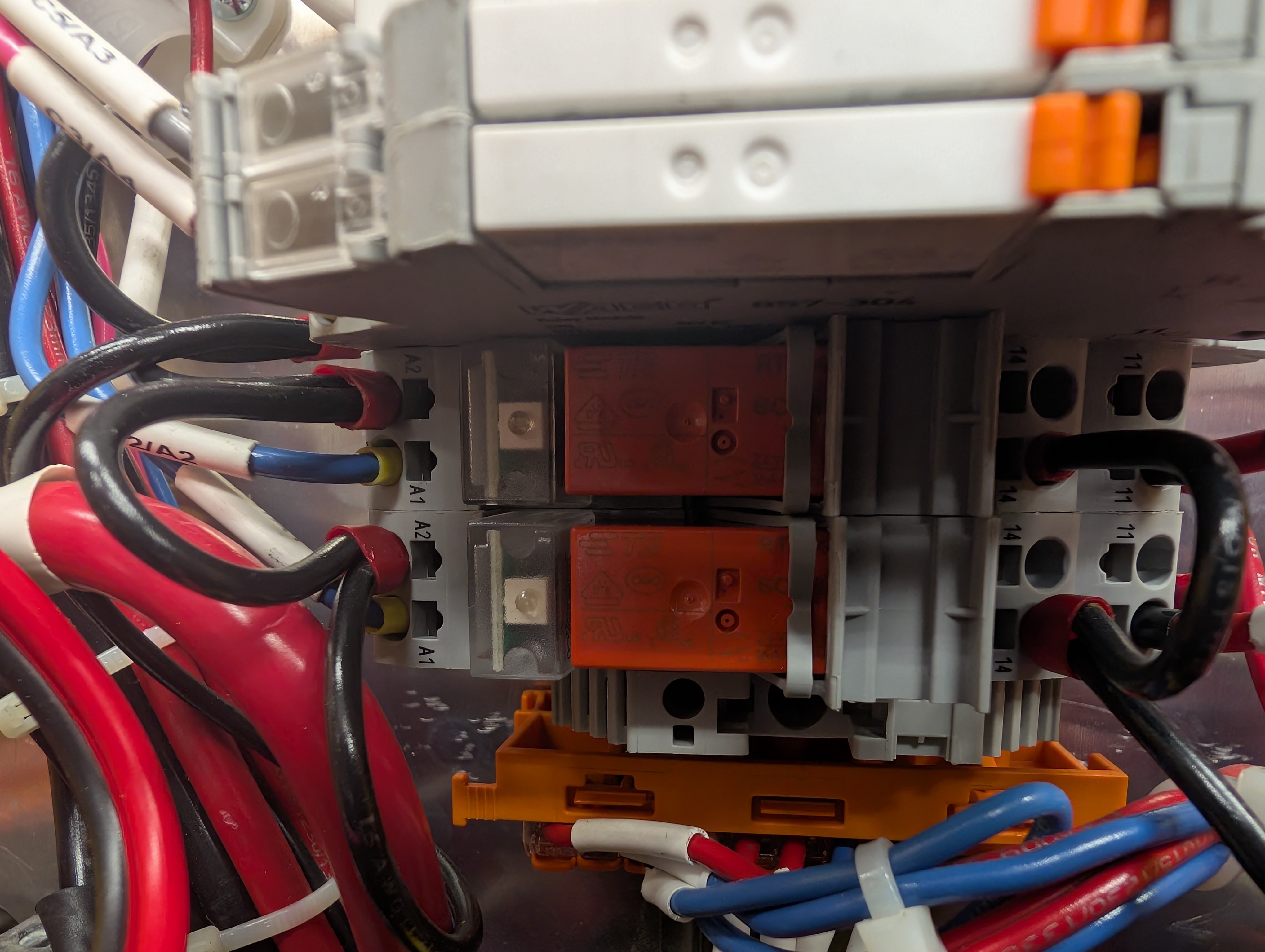
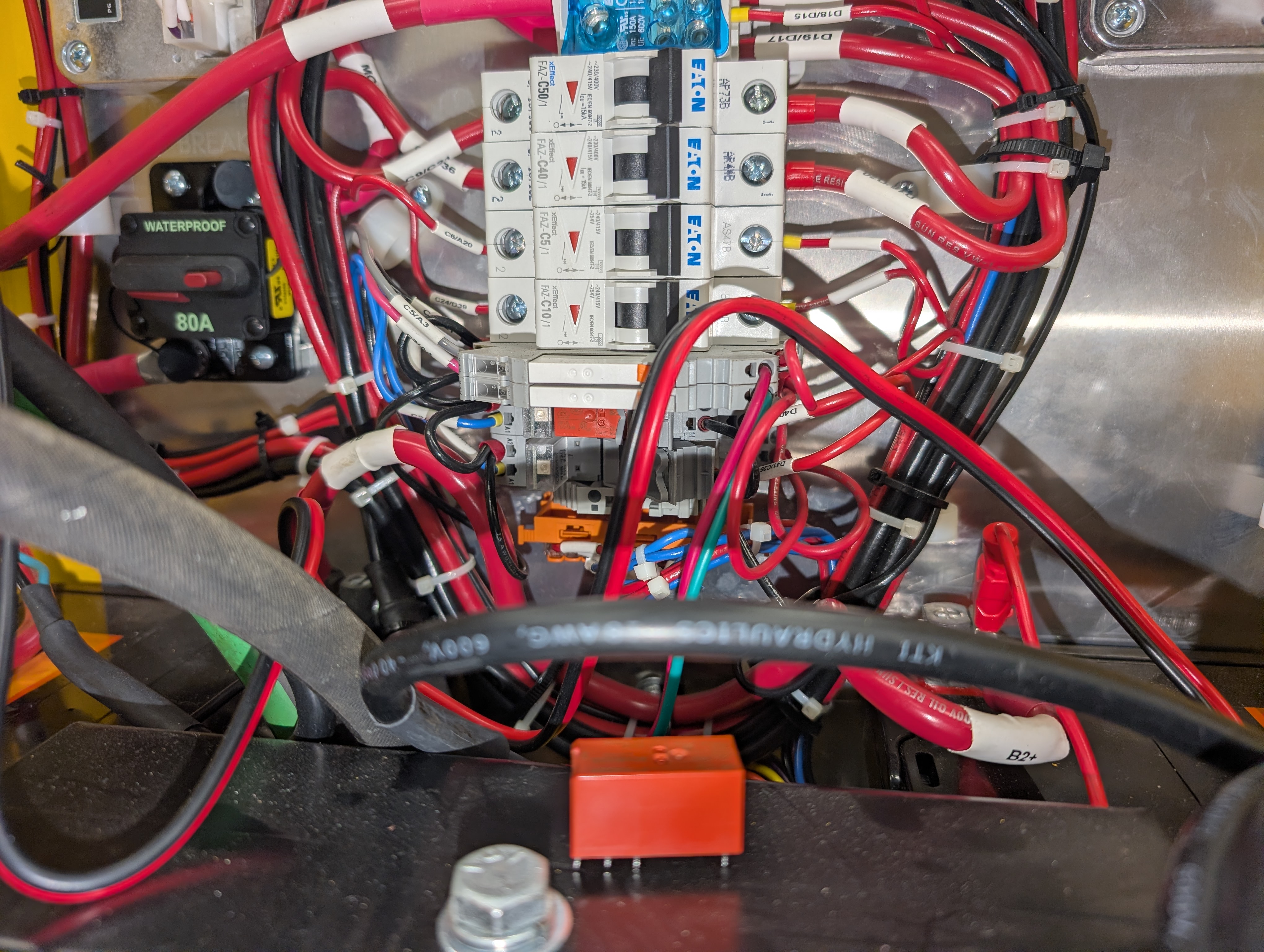
- The relays. The two red wires land on the output terminals of two WAGO relay modules stacked at the bottom of the rail (photos 8–9), one wire per module. These two relays are the jib arm's up/down switch, and they are the subject of the rest of this report.
2. How the relays drive the jib, and why a welded contact means "up forever"
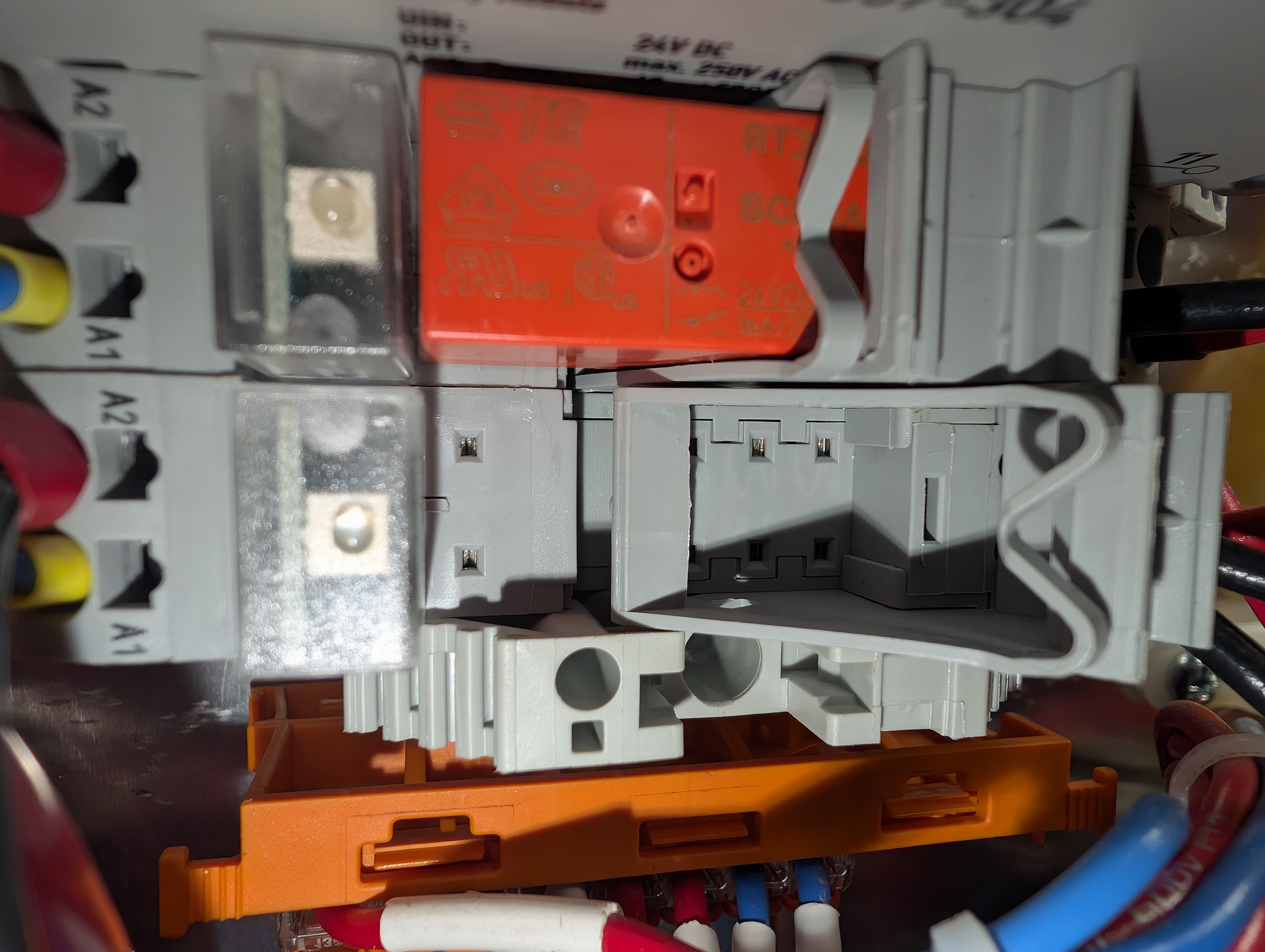
The two relays sit one above the other at the bottom of the DIN rail, each in a WAGO 788-304 relay module. Their common terminals (11) are tied together by a short black loop, and each module's normally-open output (14) feeds one of the two drive wires that leave the enclosure in the actuator cable. Traced end to end:
| Conductor | At the Deutsch plug (outside) | Inside the enclosure | Lands on |
|---|---|---|---|
C25 / D40 | white | red | Upper module, output 14 |
C26 / D41 | red | red | Lower module, output 14 |
C27 / D42 | black | black | Return; does not pass through the relays |
Which of the two relays is "up" and which is "down" was not determined; the meter check below settles it.
Pressing up or down energises one relay coil (terminals A1/A2). That relay's contact closes for as long as the button is held, powering one drive wire and running the actuator in that direction. Release the button and the contact opens.
When a contact welds, that output stays live with the coil de-energised. The actuator is told to extend constantly, the buttons can no longer change anything, and it runs until it reaches the end of its travel. That matches the observed behaviour exactly.
Welding is the expected end of life for this relay in this job. A reversing DC motor is an inductive load that arcs across the contacts on every break. The relays carry a 2018 date code (week 40), so these silver-nickel contacts have been absorbing that arc for eight years.
Confirming which relay
- Power the lift down (80 A main breaker, or disconnect the battery lead).
- Eject each orange relay with the gray lever on its module (photos 12 and 13).
- Meter across the relay's COM and NO pins. A healthy relay reads open; the welded one reads near 0 Ω.
- Alternative live test: with only the suspect relay removed, the actuator should stop extending.
3. Parts
| Part | Description | Qty | Notes |
|---|---|---|---|
RT314024 | TE Connectivity / Schrack RT1 power relay, 1 changeover, 16 A / 250 VAC, 24 VDC coil | 2 | Plug-in; no wiring disturbed. Stocked by DigiKey, Mouser, Newark, RS. |
788-304 | WAGO relay module, 24 VDC, 1 CO 16 A, 15 mm, push-in spring clamps, ejector clip, LED | 0–2 | Only if a base itself is damaged. Ships with an RT314024 already fitted. |
Terminals on the WAGO modules are spring clamps, not screws: release a wire by pressing a small screwdriver into the slot beside it.
4. Other observations
- Mast-lift hydraulic reservoir is below the MIN line (photo 5). Unrelated to the jib fault, but top up before returning to service.
- Excellent serviceability: the entire mast-lift hydraulic power unit unbolts and hangs on the control-arm pivot (photos 6–7), so the relay modules at the bottom of the DIN rail can be reached without a second pair of hands. Credit to Hardy Lifts for that detail.
- Other components identified: PG Drives Technology
D51430.05motor controller, Eaton FAZ breakers C50 / C40 / C5 / C10, 80 A waterproof main breaker, two Duracell Ultra 12 V SLA batteries, gray Deutsch DT 3-pin connector on the actuator cable.
5. Photo record
All originals are full-resolution camera files with the EXIF capture time intact; location data and camera identification have been removed. Click any thumbnail for the full-resolution file. The same set is in the Google Photos album. A machine-readable index is in images/MANIFEST.md.
10 September 2026 — initial inspection
11 September 2026 — relay identification
6. Status
- 2026-09-10: Hardy Lifts contacted; they offered a parts invoice or a service visit. Machine is out of warranty.
- 2026-09-11: relay identified as a commodity plug-in part; price requested from Hardy Lifts.
- Pending: obtain two RT314024, swap, top up mast hydraulic oil, function test the jib in both directions.
Page maintained by Jefferson Garman. Photos and text may be shared with Hardy Lifts for support purposes. Jib arm product image © Hardy Lifts, reproduced for reference.