Project SLOW-SWEEP
1. Project Overview
The ComXim 15.8-inch motorized display turntable is a commercially available product designed for product photography and retail display. Its stock speed range spans 0.5–1.28 min/rev (30–77 seconds per revolution). The goal of Project SLOW-SWEEP is to achieve rotation at 1 revolution per 20–30 minutes — a 15–60× slowdown — with bidirectional capability: a full CW sweep followed by a full CCW return.
The project proceeded in three phases. Phase 1 (complete): non-destructive investigation via UART interception, IR reverse-engineering, encoder feedback, and software closed-loop control. Phase 1.5 (June 29): UART exploration of all four STC UART headers and motor drive hardware assessment. All UART ports found to carry only a fixed 1Hz keepalive — no useful telemetry. Single L298N under heatsink confirmed driving both motors in parallel. Phase 2 (Tuesday): bypass the ComXim mainboard entirely and drive both stepper motors in parallel from a single L298N H-bridge board controlled by the ESP32-S3 — mirroring the ComXim’s own architecture.
2. Hardware Inventory
| Component | Part | Key Specifications |
|---|---|---|
| Turntable | ComXim 15.8″ Heavy Duty | Mainboard: MTxM_V6.01, dated 2025.02.28. Website: comxim.com |
| Turntable MCU | STC 8H8K64U | 8051-core, LQFP-32, 64KB flash, closed firmware. Handles IR decode, motor sequencing, speed ramping, buzzer. |
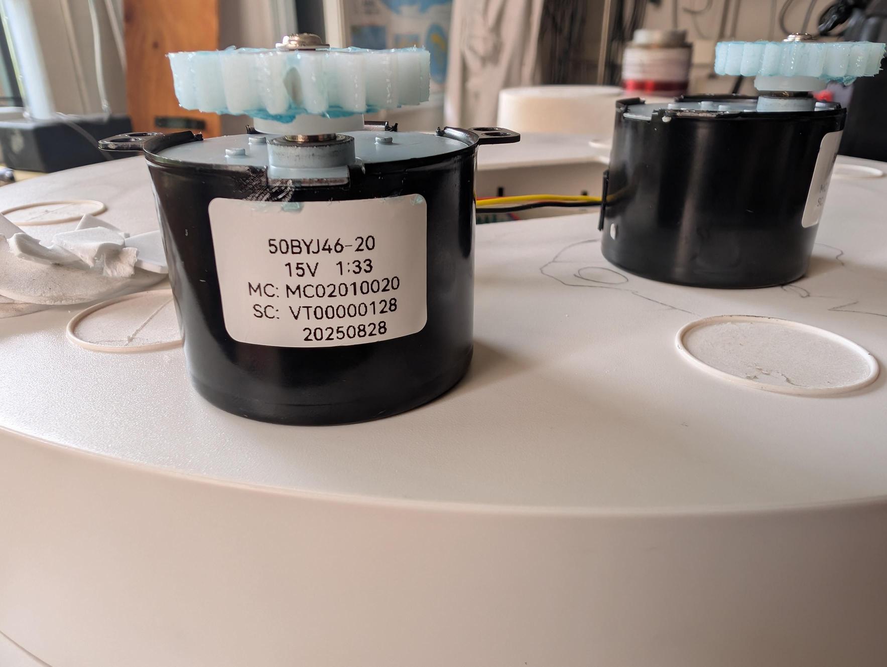
| Drive motors | 2× 50BYJ46-20 | 15V bipolar stepper, 1:33 internal planetary gear ratio. Both motors drive a common ring gear in sync. |
| Controller | ESP32-S3-WROOM-1 N16R8 | 16MB flash, 8MB PSRAM, dual USB-C. /dev/ttyACM0. IR on GPIO16, encoder A/B on GPIO5/6, UART sniffer GPIO17/18. |
| IR Transmitter | ATOM S3 (M5Stack) | Accepts NEC codes over serial, transmits as 38kHz IR. /dev/ttyACM1. Software-controlled remote substitute. |
| Encoder | LPD3806-600BM-G5-24C | 600 PPR quadrature. 4× decode = 2400 counts/rev = 0.15°/count. 5–24V supply. |
| Microphone | Plantronics Blackwire 5220 | USB headset, ALSA hw:3,0, mono, 44100Hz. Used for beep detection to confirm IR command receipt. |
| Motor driver (Phase 2) | HiLetgo L298N ×4 pack | Dual H-bridge, 2A continuous per channel, up to 46V motor supply. One unit drives both steppers with all coils wired in parallel — identical to ComXim architecture. |
3. Chronology
Getting Inside
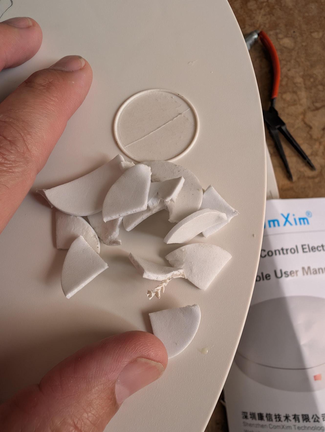
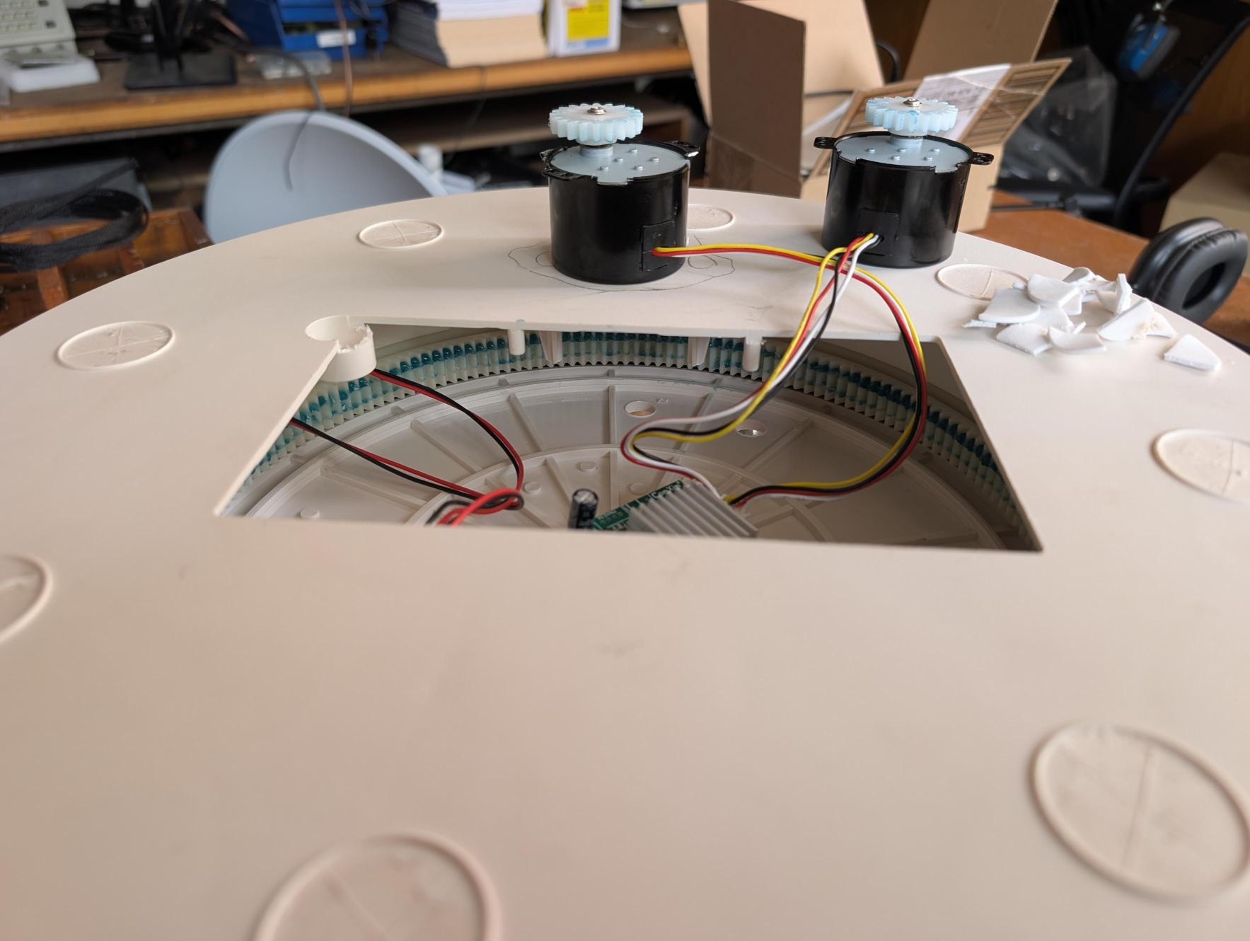
The ComXim has no visible exterior screws. The bottom panel has circular foam pads. Removing them revealed screw covers but no fasteners — the foam pads were destroyed in this search. Access is via a large rectangular window milled into the top panel.

Drive System
Through the access window, two 50BYJ46-20 bipolar stepper motors are visible mounted above the cavity, driving a large toothed ring gear belt via pinion gears. Both motors are identical: 15V, 1:33 internal planetary gear reduction, bipolar (4-wire) configuration.
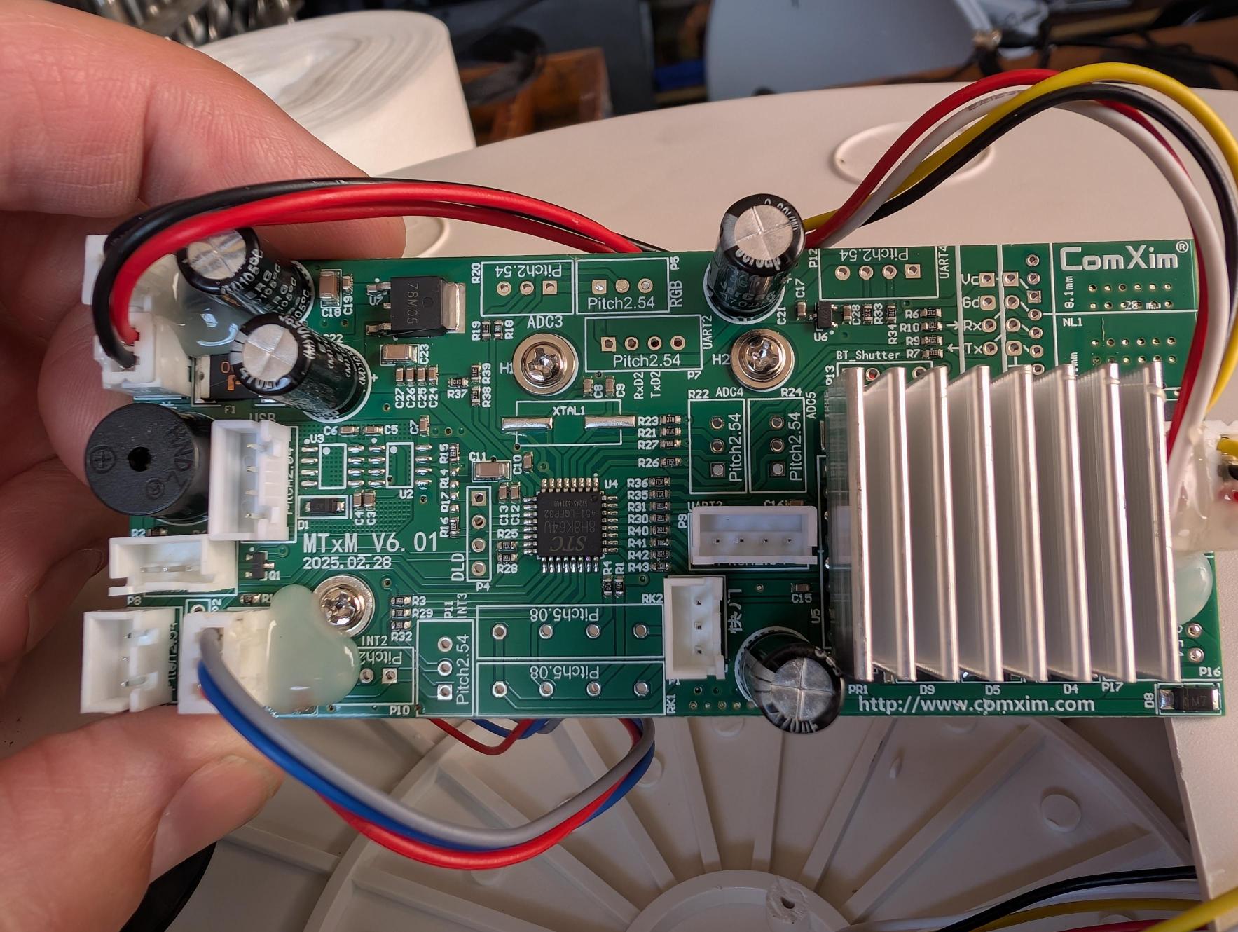
ComXim MTxM_V6.01 Control Board
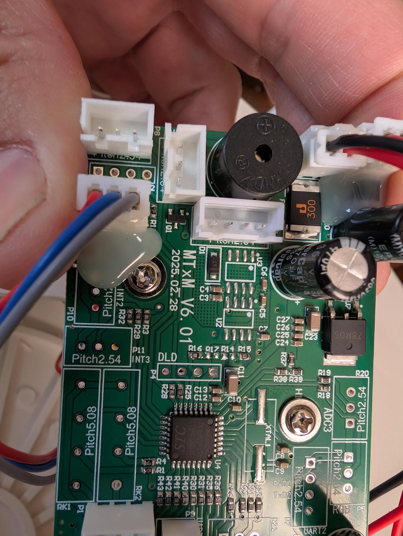
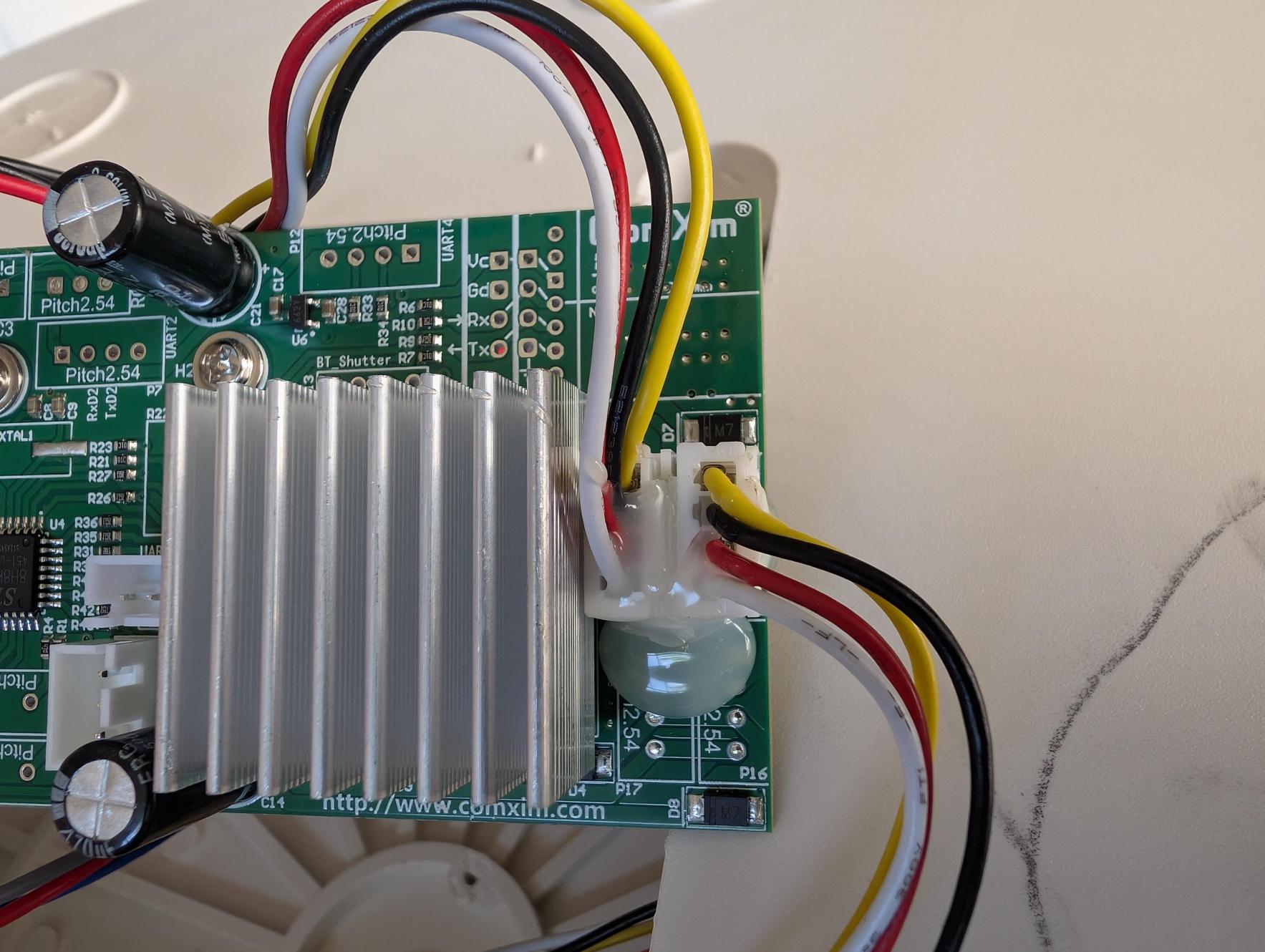
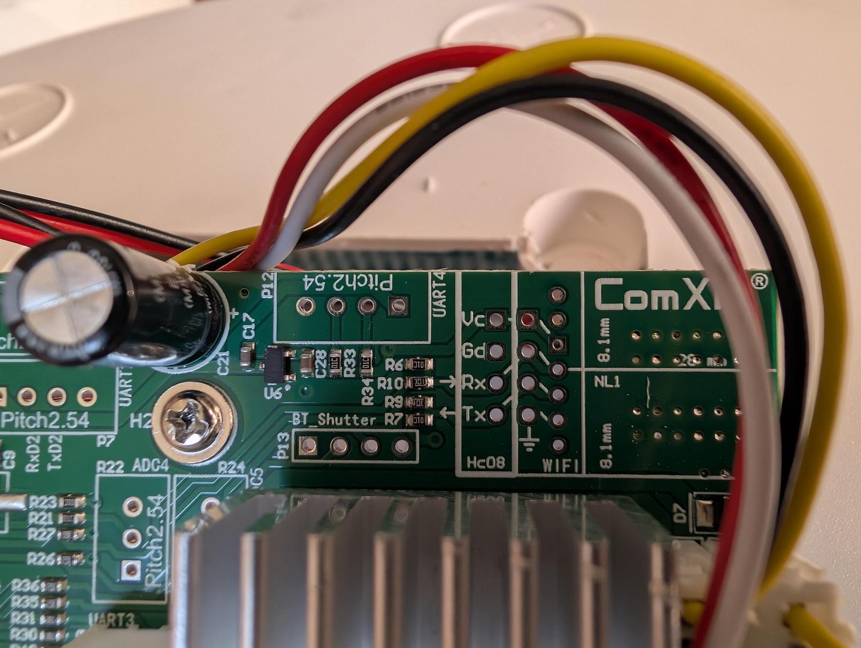
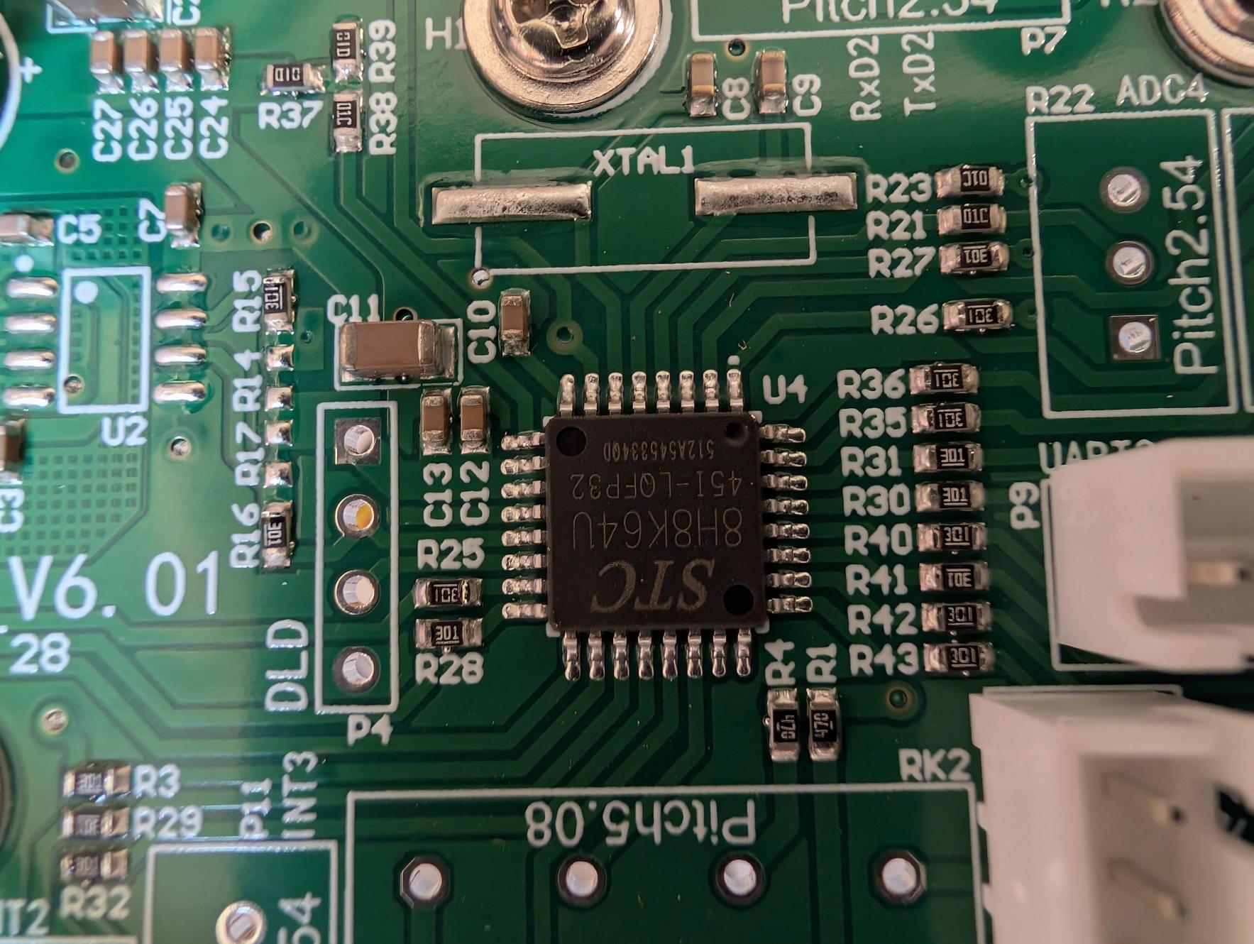
The mainboard sits flat inside the cavity. Key components identified through photography:
- STC 8H8K64U — 8051-core MCU, LQFP-32. All turntable logic runs here: IR decoding, motor sequencing, speed ramping, direction control, buzzer patterns.
- Motor driver — Under a large aluminum heatsink on the right third of the board. Likely an L298N or equivalent.
- UART4 test pads — Labeled Vc, Gd, Rx, Tx. These were the first investigation target.
- Buzzer — Round piezo cylinder, top-left. Produces command-acknowledgment beeps.
- IR receiver connector — Labeled IR进控 / INT1. Three-pin JST on the left side.
The Serial Strategy
The initial plan assumed the ComXim firmware uses an ASCII or binary serial protocol — similar to other motorized camera or display products — on the UART4 test pads labeled on the mainboard. The ESP32-S3 was wired with GPIO18 (RX) to the ComXim Tx pad and GPIO17 (TX) to the ComXim Rx pad, sharing ground. The Vc pad was deliberately left unconnected to avoid exposing the ESP32’s 3.3V logic to an unknown voltage rail.


Result: Zero Traffic at All Baud Rates
Monitored at 9600, 19200, 38400, 57600, and 115200 baud. No bytes observed under any operating condition — not at boot, not during button presses, not during motor movement. The UART4 pads are an unpopulated programming/debug interface, inactive in the shipped firmware. The STC chip controls everything via GPIO and internal PWM. There is no serial command set.
The ASCII injection plan was abandoned. The project pivoted to IR protocol reverse engineering.
IR Receiver Tap
With serial ruled out, the IR receiver connector was tapped with monitoring wires, allowing the ESP32 to see the same demodulated NEC signal that the STC chip receives without interrupting normal remote operation. The ATOM S3 on /dev/ttyACM1 was confirmed capable of transmitting arbitrary NEC frames via serial commands, acting as a fully software-controlled remote.


LPD3806-600BM-G5-24C Encoder
A LPD3806-600BM-G5-24C rotary encoder was mechanically coupled to the turntable ring gear. With 600 PPR and 4× quadrature decode in firmware, this gives 2400 counts per revolution = 0.15° per count. Wiring: RED=Vcc (5V from USB), BLK=GND, GRN=Channel A (GPIO5), WTI=Channel B (GPIO6), GND=shield ground.


Firmware Architecture (src/main.cpp)
Three parallel tasks run on the ESP32:
- IR Decoder (GPIO16): ISR captures every edge timing. After 12ms silence, decodes NEC 32-bit frame. Output:
[IR] -> NEC decoded: bits=32 value=0x???????? - Quadrature Encoder (GPIO5/6): ISR-driven lookup table decoder, fires every state change. Output:
[ENC] counts=NNNN deg=NNN.NN - Heartbeat: Output:
[ALIVE] millis=NNN enc=NNN A=N B=Nonce per second
Git commit 8c495d5: “Initial commit: Project SLOW-SWEEP Phase 1 complete” — June 25, 2026.
NEC Protocol Reverse Engineering
ComXim remote uses NEC protocol, address 0xDF00. 32-bit frame layout:
Bits 31-24: ~command (inverted)
Bits 23-16:  command byte  <-- correct extraction field
Bits 15-8:   address high (0xDF)
Bits  7-0:   address low  (0x00)
Bug: IR Command Always Decoded as 0x00
Initial parser: int(val, 16) & 0xFF — always returned address low byte (0x00). Every command appeared unknown. Fix: (int(val, 16) >> 16) & 0xFF extracts bits 23–16 (the actual command byte).
Known Command Map
| Code | Function | Code | Function |
|---|---|---|---|
0x40 | step | 0x45 | continuous |
0x41 | ccw | 0x02 | 45° |
0x42 | startstop | 0x07 | 180° |
0x43 | slowdown | 0x0A | speedup |
0x44 | cw | 0x11 | swing |
0x1B | 90° | 0x08, 0x09 | MYSTERY — avoid |
ComXim Beep Vocabulary
| Count | Meaning |
|---|---|
| 1 beep | Command acknowledged — motor started, or direction set |
| 2 beeps | Move interrupted — startstop received while motor was mid-move (our stop signal) |
| 0 beeps | Move completed naturally (reached end of preset angle) |
| 3 beeps | Boot / power-on sequence |
Speed Range & Critical Findings
Critical Finding: Speed Gap Cannot Be Closed via IR
Minimum stock speed (1.28 min/rev) is 15–20× too fast. No IR command can make the ComXim run slower than its firmware floor. Additionally, all step-angle presets scale linearly with motor speed — the same 6° step command produces ~90° at default speed. Native step commands are unusable for precision slow motion.
Backlash: CW→CCW reversal showed a 242.25° deadband. Mitigation: always sweep a full CW rotation then full CCW — never reversing mid-sweep.
Precision test: 180°×2 CW + 180°×2 CCW returned within 1.35° of home mark. Excellent mechanical accuracy.
Closed-Loop Control Strategy
Run continuous mode at minimum speed → watch encoder stream → send stop when encoder count reaches (target − 6 counts overshoot compensation) → wait out remaining interval. This achieves any arbitrarily slow rotation speed by controlling the dwell time between steps.
Bugs Fixed in slow_sweep.py
- Step 1 +38° overshoot — Table still coasting from prior test. Fix:
wait_stopped()at top of each step. - Hang after step 2 —
read_enc_live()blocked forever if motor never started. Fix: 1-beep confirmation with 3 retries + 60s absolute timeout. - TypeError on call —
micadded to function signature but call site not updated. Fixed. - Beep threshold too high — 8× ambient unreliable. Lowered to
max(ambient × 1.3, 50). - Mic wrong device/mode — Laptop mic unreliable. Switched to USB headset hw:3,0, changed -c 2 to -c 1.
4. IR Scan Results
All measurements at maximum speed (25× speedup). Same commands produce approximately 90° at default speed. Scan run June 26, 15:46–15:55.
| NEC Code | Angle Measured | Direction | Duration | Notes |
|---|---|---|---|---|
0x01 | 102.75° | CCW | 8.0s | |
0x03 | 15.0° | CCW | 1.0s | |
0x04 | 7.35° | CCW | 0.0s | |
0x05 | 10.35° | CCW | 0.0s | |
0x06 | 28.5° | CCW | 2.0s | |
0x08 | 0° | none | — | MYSTERY — beep but no movement. Avoid. |
0x09 | 0° | none | — | MYSTERY — possible remote lock. Avoid. |
0x0C | 168.75° | CCW | 14.0s | ≈180° preset |
0x0D | 108.6° | CCW | 8.0s | ≈90° preset |
0x12 | 11.55° | CCW | 0.0s | |
0x15 | 6.9° | CCW | 0.0s | Smallest confirmed step at MAX speed |
0x18 | 81.0° | CCW | 6.0s | ≈90° preset |
0x19 | 16.95° | CCW | 1.0s | |
0x1A | 45.3° | CCW | 3.0s | ≈45° preset |
0x1C | 44.55° | CCW | 4.0s | ≈45° preset |
0x1D | 44.1° | CCW | 4.0s | ≈45° preset |
0x20 | 45.9° | CCW | 4.0s | ≈45° preset |
5. Full Sweep Performance
Run June 26, 17:51–19:01+. 151 steps, 6° target, 25s interval, CCW, minimum motor speed.
Overrun Pattern: All 47.9–52.3°
Ten steps overran to approximately 49–52° (not random — nearly identical magnitudes). Most likely cause: IR stop command not received by turntable on those steps; motor ran approximately 10 extra seconds. Recovery was immediate on the next step.
Beep Pattern During Operation (Expected)
Every step: 1 beep then 2 beeps. This is correct by design: 1 beep = "continuous" acknowledged (motor starts); 2 beeps = "startstop" while moving (motor interrupted at target). The 6.6% overrun rate is the motivation for Phase 2 direct motor control.
6. Key Negative Results
| Finding | Impact | Status |
|---|---|---|
| UART4 pads silent — no serial protocol exists in shipped firmware | Half-day investigation, ASCII injection plan abandoned entirely | Dead end |
| Stock minimum speed (1.28 min/rev) is 15–20× too fast for target | Cannot reach 20–30 min/rev via IR commands alone | Worked around (Phase 1) |
| Step angle scales linearly with motor speed | 6° step command produces ~90° at default speed; native steps unusable for slow motion | Worked around via continuous+stop |
| Laptop internal mic (ALC3226) unreliable | Beep detection required codec gain fix, still marginal at distance | Solved: Plantronics USB headset hw:3,0 |
| Commands 0x08, 0x09: beep but no visible movement | Unknown modal function — possible remote lock command | Avoided permanently |
| IR stop reliability: 6.6% failure rate (10/151 steps overran to ~50°) | Unacceptable for production use; not random — systematic IR reception failures | Root cause: drives Phase 2 L298N plan |
7. Source Code
src/main.cpp — ESP32-S3 Firmware
IR decoder (ISR edge capture → NEC decode on GPIO16), quadrature encoder (lookup-table ISR on GPIO5/6), UART sniffer passthrough (GPIO17/18), 1Hz heartbeat. Built with PlatformIO / Arduino framework.
#include <Arduino.h>

// GPIO17/18 avoid the octal-PSRAM pins (35-37) and the native USB-Serial/JTAG
// pins (19/20) reserved on this N16R8 module.
#define COM_RX_PIN 18  // ESP32 RX1 <- ComXim Tx
#define COM_TX_PIN 17  // ESP32 TX1 -> ComXim Rx
#define BAUDRATE 115200

// IR receiver OUT line (gray wire), confirmed via press/release test.
// Tapped through a 10k series resistor.
#define IR_PIN 16

// LPD3806-600BM quadrature encoder: 600 PPR, open-collector NPN outputs.
// Pulled up to 3.3V via external 10k resistors. 4x decode = 2400 counts/rev.
#define ENC_A_PIN 5
#define ENC_B_PIN 6
#define ENC_COUNTS_PER_REV 2400

volatile int32_t encPosition = 0;
volatile uint8_t encPrevState = 0;

// Lookup table: index = (prevAB << 2) | currAB, value = direction step
static const int8_t ENC_TABLE[16] = {
  0, +1, -1,  0,
 -1,  0,  0, +1,
 +1,  0,  0, -1,
  0, -1, +1,  0
};

void IRAM_ATTR encISR() {
  uint8_t a = digitalRead(ENC_A_PIN);
  uint8_t b = digitalRead(ENC_B_PIN);
  uint8_t currState = (a << 1) | b;
  encPosition += ENC_TABLE[(encPrevState << 2) | currState];
  encPrevState = currState;
}
#define IR_BUF_SIZE 256

volatile uint32_t irTimes[IR_BUF_SIZE];
volatile uint8_t irLevels[IR_BUF_SIZE];
volatile uint16_t irHead = 0;
volatile uint16_t irTail = 0;

void IRAM_ATTR irISR() {
  uint16_t next = (irHead + 1) % IR_BUF_SIZE;
  if (next != irTail) {
    irTimes[irHead] = micros();
    irLevels[irHead] = digitalRead(IR_PIN);
    irHead = next;
  }
}

void setup() {
  Serial.begin(BAUDRATE);
  while (!Serial) { ; }

  Serial1.begin(BAUDRATE, SERIAL_8N1, COM_RX_PIN, COM_TX_PIN);

  pinMode(IR_PIN, INPUT);
  attachInterrupt(digitalPinToInterrupt(IR_PIN), irISR, CHANGE);

  pinMode(ENC_A_PIN, INPUT_PULLUP);
  pinMode(ENC_B_PIN, INPUT_PULLUP);
  encPrevState = (digitalRead(ENC_A_PIN) << 1) | digitalRead(ENC_B_PIN);
  attachInterrupt(digitalPinToInterrupt(ENC_A_PIN), encISR, CHANGE);
  attachInterrupt(digitalPinToInterrupt(ENC_B_PIN), encISR, CHANGE);

  Serial.println();
  Serial.println("==============================================");
  Serial.println("PROJECT SLOW-SWEEP: IR DECODE + ENCODER");
  Serial.println("==============================================");
  Serial.printf("IR on GPIO%d, Encoder A=GPIO%d B=GPIO%d\n", IR_PIN, ENC_A_PIN, ENC_B_PIN);
}

#define MAX_EDGES 140
uint32_t edgeTimes[MAX_EDGES];
uint8_t edgeLevels[MAX_EDGES];
int edgeCount = 0;
uint32_t lastEdgeMicros = 0;
bool inFrame = false;

void decodeAndPrint() {
  if (edgeCount < 3) return;

  Serial.print("[IR FRAME] edges=");
  Serial.print(edgeCount);
  Serial.print("  ");
  for (int i = 0; i + 1 < edgeCount && i < 70; i++) {
    uint32_t dur = edgeTimes[i + 1] - edgeTimes[i];
    Serial.print(edgeLevels[i] == 0 ? "M" : "S");
    Serial.print(dur);
    Serial.print(' ');
  }
  Serial.println();

  // Attempt NEC-style decode: leading mark ~9000us, then space ~4500us (new)
  // or ~2250us (repeat), then 32 bits of mark(~562us)+space(562=0 / 1687=1).
  uint32_t mark0 = edgeTimes[1] - edgeTimes[0];
  uint32_t space0 = edgeTimes[2] - edgeTimes[1];

  if (mark0 > 8000 && mark0 < 10000) {
    if (space0 > 1800 && space0 < 2700) {
      Serial.println("[IR] -> NEC REPEAT");
      return;
    }
    if (space0 > 3800 && space0 < 5200) {
      uint32_t value = 0;
      int bits = 0;
      int idx = 2;  // index of bit0's mark-start edge
      while (idx + 2 < edgeCount && bits < 32) {
        uint32_t bitSpace = edgeTimes[idx + 2] - edgeTimes[idx + 1];
        uint8_t bit = (bitSpace > 1000) ? 1 : 0;
        value |= ((uint32_t)bit << bits);
        bits++;
        idx += 2;
      }
      Serial.printf("[IR] -> NEC decoded: bits=%d  value=0x%08lX\n", bits, (unsigned long)value);
      return;
    }
  }
  Serial.println("[IR] -> (raw frame, did not match NEC leader timing)");
}

void loop() {
  // ComXim Mainboard -> Laptop CLI
  if (Serial1.available()) {
    Serial.print("[COMXIM]: ");
    while (Serial1.available()) {
      Serial.print((char)Serial1.read());
    }
  }

  while (irTail != irHead) {
    uint32_t t = irTimes[irTail];
    uint8_t lvl = irLevels[irTail];
    irTail = (irTail + 1) % IR_BUF_SIZE;

    if (!inFrame) {
      edgeCount = 0;
      inFrame = true;
    }
    if (edgeCount < MAX_EDGES) {
      edgeTimes[edgeCount] = t;
      edgeLevels[edgeCount] = lvl;
      edgeCount++;
    }
    lastEdgeMicros = t;
  }

  if (inFrame && (micros() - lastEdgeMicros > 12000)) {
    decodeAndPrint();
    inFrame = false;
    edgeCount = 0;
  }

  // Report encoder position whenever it changes
  static int32_t lastReportedPos = 0;
  int32_t pos = encPosition;
  if (pos != lastReportedPos) {
    float degrees = (float)pos * 360.0f / ENC_COUNTS_PER_REV;
    Serial.printf("[ENC] counts=%ld  deg=%.2f\n", (long)pos, degrees);
    lastReportedPos = pos;
  }

  static uint32_t lastHeartbeat = 0;
  if (millis() - lastHeartbeat > 1000) {
    lastHeartbeat = millis();
    int a = digitalRead(ENC_A_PIN);
    int b = digitalRead(ENC_B_PIN);
    Serial.printf("[ALIVE] millis=%lu  enc=%ld  A=%d B=%d\n", (unsigned long)lastHeartbeat, (long)encPosition, a, b);
  }

  // Laptop CLI -> ComXim Mainboard
  if (Serial.available()) {
    String cmd = Serial.readStringUntil('\n');
    cmd.trim();
    if (cmd.length() > 0) {
      if (!cmd.endsWith(";")) {
        cmd += ";";
      }
      Serial.print("[INJECTING]: ");
      Serial.println(cmd);
      Serial1.print(cmd);
    }
  }
}
monitor.py — Live Serial Monitor
Real-time terminal monitor: decodes and logs encoder position, named IR commands, and beep count events. Mic via ALSA arecord, 20ms chunk RMS analysis.
"""
PROJECT SLOW-SWEEP — Live monitor with beep counting
Watches: encoder position, IR frames, and mic beep patterns simultaneously.
Run: python3 monitor.py
Tail: tail -f monitor.log
"""

import serial, time, subprocess, threading, sys
import numpy as np

LOG = "/home/person/Desktop/Turntable_Hacking/monitor.log"
WROOM_PORT = "/dev/ttyACM0"
MIC_DEVICE = "hw:3,0"
MIC_RATE   = 44100

# ── Logging ──────────────────────────────────────────────────────────────────

def log(msg, tag=""):
    ts = time.strftime("%H:%M:%S.") + f"{int(time.time()*10)%10}"
    prefix = f"[{tag}]" if tag else ""
    line = f"[{ts}] {prefix} {msg}"
    print(line, flush=True)
    with open(LOG, "a") as f:
        f.write(line + "\n")

# ── Beep counter ─────────────────────────────────────────────────────────────

class BeepCounter:
    """
    Continuously records audio and counts distinct beeps.
    A beep = RMS above threshold for >40ms.
    A new beep = gap of >120ms silence between spikes.
    Reports beep count whenever a pattern completes (silence after beeps).
    """
    CHUNK_MS    = 20      # analyze in 20ms windows
    MIN_BEEP_MS = 40      # minimum duration to count as a beep
    MIN_GAP_MS  = 120     # silence gap to separate beeps
    REPORT_MS   = 400     # silence after last beep before reporting

    def __init__(self, threshold=500):
        self.threshold = threshold
        self._stop = threading.Event()
        self._thread = None
        self.ambient = 0.0

    def calibrate(self, seconds=2.0):
        """Measure ambient noise floor."""
        log(f"Calibrating mic for {seconds}s...", "MIC")
        proc = subprocess.Popen(
            ['arecord', '-D', MIC_DEVICE, '-f', 'S16_LE',
             '-r', str(MIC_RATE), '-c', '1', '-d', str(int(seconds)+1)],
            stdout=subprocess.PIPE, stderr=subprocess.DEVNULL)
        data = proc.stdout.read()
        proc.kill()
        if data:
            samples = np.frombuffer(data, dtype=np.int16).astype(np.float32)
            self.ambient = float(np.sqrt(np.mean(samples**2)))
        self.threshold = max(self.ambient * 1.3, 50)
        log(f"Ambient RMS={self.ambient:.1f}  Beep threshold={self.threshold:.1f}", "MIC")

    def start(self):
        self._stop.clear()
        self._thread = threading.Thread(target=self._run, daemon=True)
        self._thread.start()

    def stop(self):
        self._stop.set()

    def _run(self):
        chunk_samples = int(MIC_RATE * self.CHUNK_MS / 1000)  # mono
        chunk_bytes = chunk_samples * 2  # 16-bit

        proc = subprocess.Popen(
            ['arecord', '-D', MIC_DEVICE, '-f', 'S16_LE',
             '-r', str(MIC_RATE), '-c', '1'],
            stdout=subprocess.PIPE, stderr=subprocess.DEVNULL)

        beep_count = 0
        in_beep = False
        beep_ms = 0
        gap_ms = 0

        while not self._stop.is_set():
            chunk = proc.stdout.read(chunk_bytes)
            if not chunk:
                break
            samples = np.frombuffer(chunk, dtype=np.int16).astype(np.float32)
            rms = float(np.sqrt(np.mean(samples**2)))
            loud = rms > self.threshold

            if loud:
                if not in_beep:
                    in_beep = True
                    beep_ms = 0
                    gap_ms = 0
                else:
                    beep_ms += self.CHUNK_MS
                    gap_ms = 0
            else:
                if in_beep:
                    gap_ms += self.CHUNK_MS
                    if gap_ms >= self.MIN_GAP_MS:
                        # Beep ended
                        if beep_ms >= self.MIN_BEEP_MS:
                            beep_count += 1
                        in_beep = False
                        beep_ms = 0
                else:
                    # In silence
                    if beep_count > 0:
                        gap_ms += self.CHUNK_MS
                        if gap_ms >= self.REPORT_MS:
                            log(f"BEEP x{beep_count}", "MIC")
                            beep_count = 0
                            gap_ms = 0

        proc.kill()
        if beep_count > 0:
            log(f"BEEP x{beep_count} (final)", "MIC")

# ── Serial monitor ────────────────────────────────────────────────────────────

def serial_monitor(wroom, enc_ref):
    """Read WROOM serial and log IR frames, encoder changes, and alive ticks."""
    last_enc = None
    last_ir_time = 0

    while True:
        try:
            line = wroom.readline().decode(errors="replace").strip()
        except:
            break
        if not line:
            continue

        if "[ENC]" in line:
            # Only log every 10 counts to avoid spam, but always log direction changes
            try:
                counts = int(line.split("counts=")[1].split()[0])
                deg_abs = round((counts - enc_ref) * 0.15, 1)
                if last_enc is None or abs(counts - last_enc) >= 10:
                    log(f"pos={counts} ({deg_abs:+.1f}deg from home)", "ENC")
                    last_enc = counts
            except:
                pass

        elif "[IR]" in line and "NEC decoded" in line:
            try:
                val = line.split("value=")[1].strip()
                cmd = (int(val, 16) >> 16) & 0xFF
                known = {
                    0x40:"step", 0x41:"ccw", 0x42:"startstop",
                    0x43:"slowdown", 0x44:"cw", 0x45:"continuous",
                    0x02:"45deg", 0x07:"180deg", 0x0A:"speedup",
                    0x11:"swing", 0x1B:"90deg",
                }
                name = known.get(cmd, f"0x{cmd:02X}")
                now = time.time()
                if now - last_ir_time > 0.5:  # debounce repeats
                    log(f"cmd={name} (0x{cmd:02X})", "IR")
                    last_ir_time = now
            except:
                pass

        elif "[ALIVE]" in line:
            try:
                enc = int(line.split("enc=")[1].split()[0])
                deg_abs = round((enc - enc_ref) * 0.15, 1)
                log(f"heartbeat enc={enc} ({deg_abs:+.1f}deg from home)", "TICK")
                if last_enc is None:
                    last_enc = enc
            except:
                pass

# ── Main ──────────────────────────────────────────────────────────────────────

log("=== MONITOR START ===")
log("Tail this log: tail -f /home/person/Desktop/Turntable_Hacking/monitor.log")

wroom = serial.Serial(WROOM_PORT, 115200, timeout=1)
time.sleep(2)
wroom.reset_input_buffer()

# Get initial encoder position as home reference
log("Reading home position...", "SETUP")
enc_home = None
deadline = time.time() + 5
while time.time() < deadline:
    line = wroom.readline().decode(errors="replace").strip()
    if "[ALIVE]" in line and "enc=" in line:
        try:
            enc_home = int(line.split("enc=")[1].split()[0])
            break
        except:
            pass
if enc_home is None:
    enc_home = 0
log(f"Home encoder position = {enc_home}", "SETUP")

# Calibrate mic
mic = BeepCounter()
mic.calibrate(seconds=2.0)
mic.start()

log("", "")
log("=== READY — start your test sequence ===")
log("SEQUENCE: reboot → mark home → 180deg x2 CW → switch CCW → 180deg x2 CCW")
log("")

# Run serial monitor (blocks until serial dies)
try:
    serial_monitor(wroom, enc_home)
except KeyboardInterrupt:
    pass
finally:
    mic.stop()
    log("=== MONITOR STOPPED ===")
slow_sweep.py — Closed-Loop Sweep Controller
Runs continuous rotation at minimum stock speed, watches encoder stream, sends stop at target angle, waits out the interval. Runs indefinitely until Ctrl+C. Beep confirmation with 3 retries and 60s absolute timeout guard.
"""
PROJECT SLOW-SWEEP — Closed-loop encoder-controlled rotation.

Runs the turntable in continuous mode at min speed, watches the encoder,
and sends STOP at exactly the target angle. Then waits out the remainder
of the step interval. Achieves ultra-slow rotation (20-30 min/rev) with
encoder-verified precision.

Physics:
  Min speed = 77s/rev = 2400 counts/rev -> 32ms/count
  IR stop latency ~200ms -> ~6 count overshoot at min speed
  We target (desired_counts - OVERSHOOT_COUNTS) to land on the mark.

Usage:
  python3 slow_sweep.py [--minutes-per-rev 25] [--direction ccw]
                        [--step-deg 6.0] [--revolutions N]
"""

import serial, time, threading, subprocess, argparse
import numpy as np

WROOM_PORT       = "/dev/ttyACM0"
ATOM_PORT        = "/dev/ttyACM1"
MIC_DEVICE       = "hw:3,0"
MIC_RATE         = 44100
LOG              = "/home/person/Desktop/Turntable_Hacking/slow_sweep.log"

COUNTS_PER_DEG   = 2400 / 360.0        # 6.667 counts/deg
OVERSHOOT_COUNTS = 6                    # ~200ms IR latency at min speed

# ── Logging ───────────────────────────────────────────────────────────────────

def log(msg):
    ts = time.strftime("%H:%M:%S")
    line = f"[{ts}] {msg}"
    print(line, flush=True)
    with open(LOG, "a") as f:
        f.write(line + "\n")

# ── Beep listener ─────────────────────────────────────────────────────────────

class BeepListener:
    CHUNK_MS    = 20
    MIN_BEEP_MS = 40
    MIN_GAP_MS  = 120
    REPORT_MS   = 400

    def __init__(self):
        self._lock   = threading.Lock()
        self._event  = threading.Event()
        self._counts = []
        self.threshold = 50
        self._stop  = threading.Event()

    def calibrate(self):
        proc = subprocess.Popen(
            ['arecord', '-D', MIC_DEVICE, '-f', 'S16_LE',
             '-r', str(MIC_RATE), '-c', '1', '-d', '2'],
            stdout=subprocess.PIPE, stderr=subprocess.DEVNULL)
        data = proc.stdout.read()
        proc.kill()
        if data:
            s = np.frombuffer(data, dtype=np.int16).astype(np.float32)
            ambient = float(np.sqrt(np.mean(s**2)))
        else:
            ambient = 0.0
        self.threshold = max(ambient * 1.3, 50)
        log(f"MIC calibrated: ambient={ambient:.1f}  threshold={self.threshold:.1f}")

    def start(self):
        self._stop.clear()
        threading.Thread(target=self._run, daemon=True).start()

    def stop(self):
        self._stop.set()

    def wait_beep(self, timeout=3.0):
        self._event.clear()
        if self._event.wait(timeout):
            with self._lock:
                return self._counts.pop(0) if self._counts else 1
        return 0

    def _run(self):
        chunk_n    = int(MIC_RATE * self.CHUNK_MS / 1000)
        chunk_bytes = chunk_n * 2
        proc = subprocess.Popen(
            ['arecord', '-D', MIC_DEVICE, '-f', 'S16_LE',
             '-r', str(MIC_RATE), '-c', '1'],
            stdout=subprocess.PIPE, stderr=subprocess.DEVNULL)

        beep_count = 0
        in_beep    = False
        beep_ms    = 0
        gap_ms     = 0

        while not self._stop.is_set():
            chunk = proc.stdout.read(chunk_bytes)
            if not chunk:
                break
            rms  = float(np.sqrt(np.mean(
                np.frombuffer(chunk, dtype=np.int16).astype(np.float32)**2)))
            loud = rms > self.threshold

            if loud:
                if not in_beep:
                    in_beep = True; beep_ms = 0; gap_ms = 0
                else:
                    beep_ms += self.CHUNK_MS; gap_ms = 0
            else:
                if in_beep:
                    gap_ms += self.CHUNK_MS
                    if gap_ms >= self.MIN_GAP_MS:
                        if beep_ms >= self.MIN_BEEP_MS:
                            beep_count += 1
                        in_beep = False; beep_ms = 0
                else:
                    if beep_count > 0:
                        gap_ms += self.CHUNK_MS
                        if gap_ms >= self.REPORT_MS:
                            with self._lock:
                                self._counts.append(beep_count)
                            self._event.set()
                            beep_count = 0; gap_ms = 0
        proc.kill()

# ── Serial helpers ────────────────────────────────────────────────────────────

def send_ir(atom, cmd, delay=0.15):
    atom.write(f"{cmd}\n".encode())
    time.sleep(delay)

def read_enc_alive(wroom, timeout=2.0):
    """Read next ALIVE heartbeat and return encoder count."""
    deadline = time.time() + timeout
    while time.time() < deadline:
        line = wroom.readline().decode(errors="replace").strip()
        if "[ALIVE]" in line and "enc=" in line:
            try:
                return int(line.split("enc=")[1].split()[0])
            except:
                pass
    return None

def read_enc_live(wroom):
    """Read next [ENC] line (fires every encoder count change during motion)."""
    while True:
        line = wroom.readline().decode(errors="replace").strip()
        if "[ENC]" in line and "counts=" in line:
            try:
                return int(line.split("counts=")[1].split()[0])
            except:
                pass

def wait_stopped(wroom, settle_s=1.5, timeout=10.0):
    """Wait until encoder is stable for settle_s seconds."""
    last_enc  = None
    last_move = time.time()
    deadline  = time.time() + timeout
    while time.time() < deadline:
        line = wroom.readline().decode(errors="replace").strip()
        if "[ALIVE]" not in line or "enc=" not in line:
            continue
        try:
            enc = int(line.split("enc=")[1].split()[0])
        except:
            continue
        if last_enc is not None and enc != last_enc:
            last_move = time.time()
        last_enc = enc
        if time.time() - last_move >= settle_s:
            break
    return last_enc

# ── Closed-loop step ──────────────────────────────────────────────────────────

def closed_loop_step(wroom, atom, mic, target_deg, direction_sign, interval_s):
    """
    Run continuous rotation, stop when encoder hits target_deg.
    direction_sign: +1 for CCW (encoder increases), -1 for CW (encoder decreases).
    Returns (actual_deg, overshoot_deg).
    """
    target_counts = int(target_deg * COUNTS_PER_DEG)
    stop_at       = target_counts - OVERSHOOT_COUNTS  # fire stop early

    cycle_start = time.time()

    # Ensure table is fully stopped before starting
    wait_stopped(wroom, settle_s=1.0, timeout=5.0)

    # Flush stale serial data, note start position
    wroom.reset_input_buffer()
    enc_start = read_enc_alive(wroom, timeout=2.0)
    if enc_start is None:
        log("WARNING: could not read start encoder position")
        enc_start = 0

    # Start continuous rotation — retry until 1-beep confirms table started
    started = False
    for attempt in range(3):
        send_ir(atom, "continuous", delay=0.1)
        b = mic.wait_beep(timeout=1.5)
        if b == 1:
            started = True
            break
        # No beep — table may already be in continuous mode, try startstop to reset then retry
        send_ir(atom, "startstop", delay=0.1)
        mic.wait_beep(timeout=1.0)
        time.sleep(0.3)
    if not started:
        return 0.0, 0.0, enc_start  # skip this step, report zero move

    # Watch encoder until stop_at counts reached (with timeout guard)
    deadline = time.time() + 60.0
    while time.time() < deadline:
        enc = read_enc_live(wroom)
        delta = (enc - enc_start) * direction_sign
        if delta >= stop_at:
            send_ir(atom, "startstop", delay=0.0)
            break
    else:
        send_ir(atom, "startstop", delay=0.0)  # safety stop on timeout

    # Let it fully stop
    enc_final = wait_stopped(wroom, settle_s=1.5, timeout=10.0) or enc_start
    actual_counts = abs(enc_final - enc_start)
    actual_deg    = actual_counts / COUNTS_PER_DEG
    overshoot_deg = actual_deg - target_deg

    # Wait out the rest of the interval
    elapsed        = time.time() - cycle_start
    wait_remaining = max(0.0, interval_s - elapsed)
    if wait_remaining > 0:
        time.sleep(wait_remaining)

    return actual_deg, overshoot_deg, enc_final

# ── Main ──────────────────────────────────────────────────────────────────────

def main():
    parser = argparse.ArgumentParser(description="SLOW-SWEEP closed-loop pulse")
    parser.add_argument("--minutes-per-rev", type=float, default=25.0)
    parser.add_argument("--direction", choices=["cw", "ccw"], default="ccw")
    parser.add_argument("--step-deg", type=float, default=6.0,
                        help="Degrees per step (default 6.0)")
    parser.add_argument("--revolutions", type=float, default=0,
                        help="Stop after N revolutions (0 = run forever)")
    args = parser.parse_args()

    steps_per_rev  = 360.0 / args.step_deg
    interval_s     = (args.minutes_per_rev * 60.0) / steps_per_rev
    direction_sign = +1 if args.direction == "ccw" else -1
    target_counts  = int(args.step_deg * COUNTS_PER_DEG)

    log("=" * 55)
    log("SLOW-SWEEP (closed-loop encoder control)")
    log(f"  direction      : {args.direction}")
    log(f"  step size      : {args.step_deg}° ({target_counts} counts)")
    log(f"  overshoot comp : {OVERSHOOT_COUNTS} counts")
    log(f"  steps/rev      : {steps_per_rev:.1f}")
    log(f"  interval       : {interval_s:.1f}s/step")
    log(f"  speed target   : {args.minutes_per_rev:.1f} min/rev")
    if args.revolutions:
        log(f"  target         : {args.revolutions} rev ({int(args.revolutions*steps_per_rev)} steps)")
    log("=" * 55)

    wroom = serial.Serial(WROOM_PORT, 115200, timeout=1)
    atom  = serial.Serial(ATOM_PORT,  115200, timeout=1)
    time.sleep(1)
    wroom.reset_input_buffer()

    mic = BeepListener()
    mic.calibrate()
    mic.start()

    enc_home = read_enc_alive(wroom) or 0
    log(f"Home encoder: {enc_home}")

    # Set min speed (25x slowdown -> 77s/rev = slowest)
    log("Setting min speed (25x slowdown)...")
    for _ in range(25):
        send_ir(atom, "0x43", delay=0.05)
    time.sleep(0.5)

    # Set direction
    dir_cmd = args.direction
    send_ir(atom, dir_cmd)
    b = mic.wait_beep(timeout=2.0)
    log(f"Direction set to {args.direction} (beep={b})")
    time.sleep(0.5)

    max_steps  = int(args.revolutions * steps_per_rev) if args.revolutions else 0
    step_count = 0
    total_deg  = 0.0
    enc_pos    = enc_home

    log("Starting sweep — Ctrl+C to stop")
    log(f"{'step':>5}  {'moved':>7}  {'overshoot':>9}  {'total':>10}  {'pos':>8}")

    try:
        while True:
            actual_deg, overshoot_deg, enc_pos = closed_loop_step(
                wroom, atom, mic, args.step_deg, direction_sign, interval_s)

            step_count += 1
            total_deg  += actual_deg
            total_rev   = total_deg / 360.0
            offset_deg  = (enc_pos - enc_home) * 0.15

            log(f"{step_count:>5}  {actual_deg:>6.1f}°  {overshoot_deg:>+8.1f}°  "
                f"{total_deg:>7.0f}° ({total_rev:.2f}rev)  {offset_deg:>+7.1f}°")

            if actual_deg > args.step_deg * 2:
                log(f"WARNING: step {step_count} overran {actual_deg:.1f}° (target {args.step_deg}°) — IR stop not received?")

            if max_steps and step_count >= max_steps:
                log(f"Target reached: {args.revolutions} rev in {step_count} steps")
                break

    except KeyboardInterrupt:
        log("")
        log(f"Stopped after {step_count} steps")
        log(f"Total: {total_deg:.1f}° = {total_deg/360:.2f} rev")

    finally:
        mic.stop()
        atom.close()
        wroom.close()

if __name__ == "__main__":
    main()
8. Phase 1.5 — UART Exploration (June 29)
With the Phase 1 sweep complete, a second investigation day was spent attempting to extract telemetry or firmware access from the ComXim mainboard via its UART headers before committing to the full L298N bypass. Four UART ports were tested, and the STC chip package was verified against the official datasheet.
STC 8H8K64U — Verified Datasheet Specifications
Package confirmed as LQFP32 (32-pin), not the 64-pin variant referenced by some distributor listings. Sources: stcmicro.com product page, features PDF, full reference manual.
- Flash: 64KB SRAM: 8.2KB Operating voltage: 1.9–5.5V
- UARTs: 4 confirmed — max baud = FOSC/4
- UART1 P3.0/P3.1 — ISP/bootloader port (only UART used by stcgal)
- UART3 default pins: P0.0 (RXD3) / P0.1 (TXD3)
- UART4 default pins: P0.2 (RXD4) / P0.3 (TXD4)


UART Test Results
All ports tested at 115200 baud via GPIO18 on the WROOM (Serial1 RX). VCC left floating. GND shared. Board TX only — no data injected. ComXim power-cycled at the start of each capture.
| Port | Signal Found | Detail | Verdict |
|---|---|---|---|
| UART2 | ### @ 1Hz | 0x23 0x23 0x23 — fixed 3-byte heartbeat, 1Hz. Unchanged across all motor states. | Dead end |
| UART3 | ### @ 1Hz | Identical output to UART2. Same firmware signal routed to both ports. | Dead end |
| UART4 | Silent | Both middle pins tried. No output at any point. Unused by firmware. | Unused |
| UART1 | Untested | ISP/bootloader on P3.0/P3.1. Header not located on board. Would require stcgal + power-cycle timing. | Future option |
The ### Heartbeat
The three-byte sequence 0x23 0x23 0x23 (“###”) appears on both UART2 and UART3 at exactly 1Hz. It did not change in response to: speed changes, direction changes, start/stop commands, or motor movement. It is a fixed firmware keepalive with no encoded state — not a useful telemetry source.
Additional IR Codes Captured
IR commands sent during UART testing captured three NEC codes not previously documented:
| Function | Full NEC Value | Command Byte |
|---|---|---|
| CCW Direction | 0xBE41DF00 | 0x41 |
| CW Direction | 0xBB44DF00 | 0x44 |
| Stop / Start | 0xBD42DF00 | 0x42 |
Motor Drive Hardware Assessment
New photos of the stepper wiring and underside of the ComXim board provided strong confirmation of the internal motor driver architecture.


Confirmed: Single L298N (POWERSO-20) Driving Both Motors in Parallel
Evidence: R500 current-sense resistor, 35V/470µF bulk cap, large POWERSO-20 thermal pad on PCB underside, single 4-wire motor connector carrying all W/R/B/Y leads. The ComXim routes both 50BYJ46-20 motors coil-in-parallel through one L298N — hence the requirement for the large heatsink under continuous operation.
Phase 2 Decision: Single L298N, Both Motors in Parallel
Both 50BYJ46-20 motors share the same internal gear ring — they are mechanically locked and must always move together. Running them from separate drivers would risk stripping the gear profile if any timing difference existed between boards. The correct architecture drives both motors from a single L298N with coils wired in parallel — exactly what the ComXim already does. This simplifies wiring to just 4 ESP32 GPIO pins and is proven to work at this current and voltage.
Current Note
At 15V with ~15Ω coil resistance, each coil draws ~1A. Two motors in parallel doubles this to ~2A per H-bridge output — right at the L298N continuous rating. At slow sweep speeds with discrete steps rather than continuous rotation, average current is well below peak. Monitor the L298N board temperature during first test runs. The HiLetgo board has a small integral heatsink; the ComXim required a large external one for continuous operation.
9. Phase 2 Plan — L298N Direct Motor Drive
Rationale
Phase 1 proved the encoder position feedback works reliably. The weak link is the IR channel: 6.6% step failure rate, limited to the ComXim firmware speed floor, and dependent on the ATOM S3 as auxiliary hardware. Phase 2 eliminates the ComXim mainboard and drives the 50BYJ46-20 bipolar steppers directly from the ESP32-S3 via an L298N H-bridge board.
Why Single L298N + Parallel Coils Works
A bipolar stepper requires two H-bridges (one per winding). One L298N = two H-bridges = one complete bipolar stepper drive. The ComXim drove both motors coil-in-parallel from a single L298N (confirmed by PCB underside thermal pad analysis). The replacement build mirrors this exactly: one L298N board, both motors in parallel, 4 ESP32 GPIO pins. Motor wire colors: White, Red, Black, Yellow. Coil pairs identified by multimeter before wiring.
Wiring Plan
Bipolar Motor Coil Identification — Multimeter Readings
Set multimeter to resistance (Ω) mode. With motors disconnected from the ComXim, probe all 6 wire-pair combinations on each motor. Exactly 2 pairs will show a resistance value (the two coils). The other 4 pairs will read OL (open circuit — no connection). Expected coil resistance for the 50BYJ46-20 at 15V: roughly 10–30Ω. Both motors should give identical results (same model).
Motor 1
| # | Wire A | Wire B | Reading | Coil? |
|---|---|---|---|---|
| 1 | White | Red | _____ Ω | |
| 2 | White | Black | _____ Ω | |
| 3 | White | Yellow | _____ Ω | |
| 4 | Red | Black | _____ Ω | |
| 5 | Red | Yellow | _____ Ω | |
| 6 | Black | Yellow | _____ Ω |
Motor 2
| # | Wire A | Wire B | Reading | Coil? |
|---|---|---|---|---|
| 1 | White | Red | _____ Ω | |
| 2 | White | Black | _____ Ω | |
| 3 | White | Yellow | _____ Ω | |
| 4 | Red | Black | _____ Ω | |
| 5 | Red | Yellow | _____ Ω | |
| 6 | Black | Yellow | _____ Ω |
Interpreting the Readings
- The 2 pairs that show resistance = Coil A and Coil B. The other 4 pairs = OL (open, different coil or no connection).
- Label them: the resistance pair is A+ (one wire) and A− (the other). Same for B. Polarity determines step direction — if the motor runs backwards, swap A+ and A− in the wiring, or invert the step sequence in firmware.
- Both motors MUST be wired identically (same color → same OUT pin) because the gear ring locks them mechanically. There is no independent operation.
- Example: White–Red = 18Ω, Black–Yellow = 18Ω, all others OL → Coil A = White/Red, Coil B = Black/Yellow. Wire White & White to OUT1, Red & Red to OUT2, Black & Black to OUT3, Yellow & Yellow to OUT4.
Bipolar Full-Step Sequence
Step  IN1  IN2  IN3  IN4    Energized coils
  1    H    L    H    L      A+ and B+
  2    L    H    H    L      A- and B+
  3    L    H    L    H      A- and B-
  4    H    L    L    H      A+ and B-

Advance forward  = CW rotation
Advance backward = CCW rotation
Speed            = microsecond delay between steps
What Is Retired
- ComXim MTxM_V6.01 mainboard — disconnected, removed from cavity
- ATOM S3 IR transmitter — no longer needed
- All NEC IR protocol logic in firmware and Python scripts
- Plantronics Blackwire 5220 — beep detection no longer needed
What Is Kept
- ESP32-S3-WROOM-1 N16R8 — primary controller, now generates step pulses
- LPD3806-600BM-G5-24C encoder — unchanged wiring, provides position verification
- 15V power supply — barrel jack repurposed directly to L298N motor supply input
Tuesday Action Items
- Identify coil pairs — Before disconnecting ComXim, use the fill-in table above (resistance mode, all 6 color combinations on each motor). Two pairs ~10–30Ω = Coil A and Coil B. Label with tape. Both motors must match.
- Wire single L298N board — Both motors in parallel: Coil A(+) of both → OUT1, Coil A(−) of both → OUT2, Coil B(+) of both → OUT3, Coil B(−) of both → OUT4. 15V to VS. GND shared. ENA/ENB jumpers ON.
- Wire ESP32 GPIOs — 4 wires only: GPIO1 → IN1, GPIO2 → IN2, GPIO3 → IN3, GPIO4 → IN4. ATOM S3 not needed — leave unplugged.
- Add step sequencer firmware — Update src/main.cpp with serial command handler:
STEP <n> <dir>advances both motors in sync through the 4-step full-step sequence. Encoder ISR unchanged. - Characterize the system — Run a known step count, read encoder delta, compute actual total gear reduction (motor 1:33 × ring gear ratio).
- Write slow_sweep_v2.py — Replace IR send_ir() calls with serial STEP commands. No beep listener needed. Same encoder closed-loop logic.
Expected Outcome
Direct firmware step control gives deterministic, lossless rotation at any speed. The 6.6% IR overrun rate drops to 0%. Any speed from milliseconds-per-step to seconds-per-step is achievable — the 25 min/rev target is trivial. The encoder provides continuous sanity checking that no steps were skipped under load.
10. Phase 2 Results — Thermal Testing & Calibration (June 30)
Full-Step Baseline (Test 1)
Initial wiring complete. Firmware flashed with full-step 4-state table (7200 steps/rev). A sustained rotation test immediately revealed thermal problems: the L298N surface temperature reached 150°F+ and the driver triggered its internal thermal shutdown multiple times, causing audible stall-and-restart pauses mid-rotation. The turntable did not complete a full revolution.
Root Cause: Voltage-Mode Drive at Full Load
Two motors in parallel = ~9Ω effective coil resistance per channel. At 15V: I ≈ 1.67A per channel. With both channels energised simultaneously (full-step), the L298N dissipates roughly 6W continuously (Vce_sat × I × 2 channels). The L298N POWERSO-20 with its stock heatsink cannot sustain this indefinitely — junction temperature exceeds the 150°C thermal cutoff. The ComXim board used the R500 sense resistors for current-mode chopping, which both limits current and enables microstepping — explaining why it ran cooler and smoother.
Half-Step Upgrade (Test 2)
Firmware updated to an 8-state half-step sequence. The single-coil intermediate states draw half the current (power = I²R, so ¼ the heat per state), reducing average dissipation by ~35%. Peak temperature dropped to 118–119°F on a continuous run. Motion was noticeably smoother and quieter than full-step. Still warm enough to be a concern for sustained runs.
Half-Step + Burst-Pause (Test 3 — Final)
Implemented thermal duty-cycle management in software: step 5° quickly (200 steps at 5ms/step ≈ 1 second), then release all coils for 3 seconds, repeat. With coils de-energised the L298N dissipates zero power and cools rapidly. Result: temperature never exceeded 95°F across the full 3× CW/CCW endurance run.
Calibration Results
| Parameter | Full-Step | Half-Step |
|---|---|---|
| Steps / revolution | 7,200 | 14,400 |
| Degrees / step | 0.050° | 0.025° |
| Steps / degree | 20 | 40 |
| Encoder counts / rev | 2,400 | 2,400 (unchanged) |
| Angular accuracy (10° test) | ±0.25° | ±0.25° |
| Peak L298N temp (sustained) | 150°F+ (thermal shutdown) | 95°F (burst-pause) |
Endurance Test — 3× CW/CCW (30 min, June 30)
6 passes × ~5 min each. Burst-pause profile: 5° burst then 3s cooldown, 72 bursts per revolution. Encoder logged at end of each pass:
| Pass | Direction | Enc Counts | Degrees | Pass Time |
|---|---|---|---|---|
| 2 | CCW | −8 | −1.2° | 04:56 |
| 3 | CW | −2,403 | −360.45° | 04:56 |
| 4 | CCW | −8 | −1.2° | 04:56 |
| 5 | CW | −2,404 | −360.60° | 04:56 |
| 6 | CCW | −7 | −1.05° | 04:56 |
Every pass completed in exactly 04:56. CW passes land within 0.6° of −360°; CCW returns within 1.2° of 0 — consistent gear-train backlash on direction reversal, not missed steps. Zero thermal cutouts.
11. Test Videos (June 30)
Three progressive tests recorded as the drive strategy evolved from full-step to half-step burst-pause.
Test 1 — Full-Step, Continuous
First live run. L298N reached 150°F+, thermal cutout triggered multiple times causing audible pauses. Rotation did not complete. Demonstrated need for either thermal management or drive-mode change.
Test 2 — Half-Step, Continuous
Firmware upgraded to 8-state half-step (14,400 steps/rev). Single-coil intermediate states reduced average current. Temperature dropped to ~119°F. Motion smoother and quieter. Still warm enough to trigger concern for sustained runs.
Test 3 — Half-Step + Burst-Pause (Final)
Software thermal management added: 5° burst at 5ms/step (~1s moving), then coils released for 3s. L298N cools to ambient during dwell. 3× CW/CCW endurance run completed — temperature never exceeded 95°F. Encoder confirmed <0.5° accuracy every pass.
12. Phase 3 Goals — July 1
Morning: 30-Minute Endurance Validation
Run a full 30-minute sustained CW/CCW test (6 passes × 5 min) with burst-pause to confirm thermal stability under extended load. Log peak temperature and encoder drift across all passes. This is the gate before MVP wiring cleanup.
WiFi AP + Web Dashboard
The ESP32-S3 serves its own access point — no external router needed. A simple page (AsyncWebServer + WebSocket) gives live readouts and controls from any phone or laptop on the bench:
- Live encoder position (counts + degrees)
- Current pass direction and burst/cooldown status
- Pause / Resume / Stop buttons (WebSocket command → firmware)
- Step rate and burst size adjustable from browser
- Optional: DS18B20 1-wire temperature sensor on any spare GPIO for live L298N heatsink temp readout (<$3, single wire + pull-up)
Temperature Sensor Note
The ESP32-S3 has no built-in temperature sensor accessible for external use. To get heatsink temperature in the dashboard, add a DS18B20 (1-wire digital, ±0.5°C accuracy) or an NTC thermistor (analog, free if salvaged) to a spare GPIO. DS18B20 is preferred — digital, no ADC calibration needed, readable in firmware with a single library call.
Customer Output: Position Voltage / RS-232 Stream
The customer wants a voltage signal proportional to turntable rotation. Options in order of simplicity:
| Option | Hardware Needed | Notes |
|---|---|---|
| RS-232 / serial stream | None (already have USB serial) | Simplest. Output CSV “angle,counts\n” at 10Hz. Customer reads with any terminal or data logger. Add MAX232 chip for true RS-232 levels if needed. |
| PWM → RC filter | 1 resistor + 1 cap (~$0.10) | Firmware outputs PWM duty cycle proportional to angle (0° = 0%, 360° = 100%). RC filter smooths to 0–3.3V DC. Cheap but ripple exists. |
| MCP4725 I²C DAC | MCP4725 breakout (~$2) | 12-bit DAC, 0–3.3V clean analog output. 2 wires (SDA/SCL). Professional quality. Discuss with customer what voltage range and scaling they need. |
Recommendation: start the customer conversation with the serial stream (zero cost, immediate) and confirm whether they need a true analog voltage, then choose DAC vs PWM+RC based on their noise tolerance.
Wiring Cleanup → MVP++
- Dress all signal wires, strain-relief USB, secure ESP32 and L298N boards
- Label motor connectors and power wires
- Verify encoder cable routing doesn’t foul rotation
- Confirm gear cavity can be re-closed with new wiring routed
Driver Upgrade Path (Future)
If continuous-rotation smooth sweeps are needed without burst-pause, replace the L298N with two DRV8825 or TMC2208 breakout boards (one per motor, ~$5–$12 each). These use current-chopping microstepping (up to 1/32 step), run cool at full speed, and require only STEP+DIR signals from the ESP32 — two GPIO pins total instead of four. TMC2208 adds stealthChop for near-silent operation. Wire both boards to the same STEP/DIR lines for guaranteed lockstep.
MVP++ Definition
Turntable rotates at any programmable rate, direction-reversible, with encoder position verification. Web dashboard gives real-time control from a phone with no laptop required. Customer position output available over serial (and optionally as an analog voltage). Wiring clean enough to close the chassis. Thermal management confirmed stable for >30 min.