
|
This page: |
Next page: |
Paraxial optics is a way of solving the propagation of light with the help of an approximate solution to the Maxwell equations of electrodynamics. The prototypical objects that describe light within this framework are the Gaussian beams. These are beams which follow the path of a light ray but include the effect of diffractive spreading.
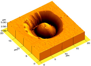 This electron micrograph shows an attempt to go beyond
paraxial optics with the intention of making a better
semiconductor laser. The dome that rises out of the
crater is a microresonator for light.
This electron micrograph shows an attempt to go beyond
paraxial optics with the intention of making a better
semiconductor laser. The dome that rises out of the
crater is a microresonator for light.
A more detailed description and theoretical study of this structure as contained in [Phys. Rev. E 62, 8677 (2000)] grew out of my collaboration with the group of Izo Abram at CNET/CNRS Bagneux (France).
The purpose of this architecture is to confine light inside the dome, just like acoustic echoes are confined in a macroscopic dome. As in the design of a concert hall, one can actually achieve focusing effects which enhance the intensity in certain parts of the dome.
The dimensions are shown in this schematic side view.
Just like a geological cross section, this plot indicates
the layers of material at the foundations of the
semiconductor dome. The Bragg mirror is a multilayer
structure that strongly reflects light when it is
incident in the proper range of angles and with the right
wavelength. The top of the dome is covered with gold
which acts as a weaker, but more robust mirror.
The most important layer in this structure is the quantum well region indicated in red. The goal of the dome is to focus light emitted from this active layer back onto it.
How was this design conceived ? Based on ray-optics considerations: it is well-known that parabolic mirrors are very efficient at focusing light in macroscopic situations, and to exploit this effect one should try to make the dome in a parabolic shape with the active layer intersecting the parabola's focus.
There are two questions that we can try to address within the ray picture:
To illustrate rays and waves in the dome cavity, the
grayscale plot here shows the electric field intensity
inside this cavity, which in its dark regions seems to
reproduce the domains of high ray density. The ray trace
shown below actually represents a single trajectory which
does not close on itself; dark regions are explored more
often by the ray.
Here is a side view of the dome. We simplify the problem by considering only the electrodynamics of this part of semiconductor structure. The Bragg mirrors are taken into account tby choosing appropriate boundary conditions (e.g. Neumann conditions). Also, the fields have to vanish on the gold mirror.
The ray picture becomes more transparent when the
resonator geometry is unfolded into a confocal double parabola, by applying a
reflection at the plane interface and keeping in mind
that according to the boundary conditions the
corresponding wave solutions are those with even parity
under this reflection.
The pure ray picture does not retain any phase information so that the distinction between even and odd solutions is not meaningful here. However, this difference will come in when one makes the connection between rays and waves using semiclassical quantization. For the escape directionality and internal caustic structure, the parity again does not make a big difference in the limit of small wavelength.
The first important observation is that the case of exactly confocal paraboloids with rotation symmetry about the central axis is in fact one of the very rare special cases where there is no chaos in the ray dynamics. Experimentally, however, there will always be slight deviations from this exact mathematical shape, especially from the confocal condition, so that we will have to consider the importance of such deviations.
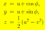
To describe what's going on in the cavity, we have to introduce a coordinate system. For axially symmetric objects, a standard thing is to use cylinder coordinates. However, in our special case the symmetry of the paraboloid shape suggests that we introduce parabolic cylinder coordinates. They are related to cartesian coordinates x, y, z as follows:
 |
 |
The meaning of the coordinate lines parameterized by u and v is shown on the righhand side. The boundary surface of the double paraboloid is parameterized by u=1 and v=1. By this choice, I have fixed the length unit in terms of which all other length scales are measured.
Find a sketch of the wave equation and its solution on the next page. The problem is integrable because the wave equation is separable in parabolic cylinder coordinates.
On this page, we focus on the ray picture because of its intuitive appeal. The first goal is to get a feeling for the general types of ray motion that are possible in the dome. The next step will be to evaluate the consequences of this structure for the wave solutions and the coupling to the outside.
The ray trajectories are equivalent to the
trajectories of a point mass undergoing specular
reflection in a "billiard", so I shall use some
terminology from classical mechanics.
Because of the rotation symmetry, the angular momentum
around the rotation axis is conserved. Let us call this
quantity ℓz. In optics, this is also referred to as
the "skewness" of a ray.
It is convenient to describe the ray motion in a
coordinate system that makes use of the rotational
symmetry. In order to be sufficiently general (so that we
can later look at non-confocal paraboloids), I simply use
cylinder coordinates,
ρ,φ,z.
Here, φ is the cyclic coordinate, canonically conjugate
to the angular momentum component around the z axis
(which is the rotation axis). The ray motion can the be
described uniquely in the two-dimensional plane spanned
by ρ and z alone. This corresponds to projecting the
trajectory onto a plane through the z axis which rotates
with the point particle. Let us first consider the
special case ℓz=0, so there is no rotation, and all
trajectories with ℓz=0 pass through the rotation
axis.
Here is the resulting plot for the special case of a
trajectory that intersects the z axis in the focal
point:
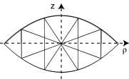
Fig.1
The complete trajectory, as shown on the left, has the
shape of a bowtie, as is well-known for confocal
mirrors.
From now on, we use the representation
on the right.
Note that the vertical axis is the radial distance from
the rotation axis, and therefore it is always positive.
Therefore the plot shows only half of the resonator. The
cut goes through the rotation axis. For technical
reasons, the plot is rotated by 90 degrees compared to
the previous representations of the dome, and only one
half of the structure is shown.
This is also the trajectory corresponding to the mode
that provides the desired focusing.
However, there are many other types of trajectories
that never go through the focal point, and still give
rise to sharp caustics. They should also correspond to
wave solutions.
Here is a typical caustic formed by following a single
ray for many reflections:
 |
Fig.2 Here, the caustic is seen as the boundary of the white space excluded from the ray paths. The ray is tangent to the caustic, giving rise to the dark shade near it. The shape of the caustic is also known: It is itself a parabola with the same focal point as the boundary parabolas, but with a different "diameter". The caustic parabola intersects the boundary at a right angle. These observations are true for all the trajectories that are not periodic, i.e. that do not close on themselves. The bowtie-trajectories shown above are periodic and therefore do not form a caustic. |
| To illustrate the situation, here is another example: | |
 |
Fig.3 This is the basic physics. Now we have to take into account the possibility of nonvanishing angular momentum, ℓz. The the rays have to avoid the z-axis, and therefore can never go through the focal point. This implies immediately that bowtie-orbits of the type shown for ℓz=0 do not exist when there is an additional rotation around the z axis. In the wave solution this would correspond to a nonvanishing azimuthal quantum number. |
The rotating frame is very useful, however, because it makes use of the rotational symmetry in the same way one would do it for solving the wave equation. And the projections of the rays onto this ρ-z plane are very closely related to the wave solutions in this plane.
One thing that stays the same in the rotating frame is the law of specular reflection: The angle with respect to the normal to the surface is the same for incident and reflected rays.
But there are new orbits that can be thought of as the offspring of the original bowtie orbit. An example is shown here:
 |
Fig.4 I call this the smily orbit. In dimensionless units, the angular momentum is ℓz=0.3. The units are chosen such that the maximum angular momentum is ℓz=1, corresponding to a ray circling around in the equatorial plane of the double parabola (z=0), tracing out the circle formed at the intersection between the two parabolas. This orbit has one thing in common with the bowtie: The rays cross the ρ-axis exactly perpendicularly. But this apparent angle is only an artifact of the rotating ρ-z plane, so the rays in reality cross the equatorial plane at some other angle. Also, they don't reach the focal point anymore, because a finite angular momentum with respect to the z axis does not allow that. The orbit is also periodic, but only in the rotating frame. In the 3D space it does not close on itself in general. I'll show real space pictures later. |
| The more general trajectories also acquire a different face. This is illustrated here: | |
 |
Fig.5 The angular momentum barrier repels trajectories from the z axis, so that a new gap appears in the caustic (on the right). Patterns like this are micked by the wave solutions |
Whenever the rays hit the plane, I record the position in the plane, and the "momentum" with which the incident ray comes in. The position in the plane can be described with the coordinates φ and ρ of the cylindrical coordinate system, setting z=0. This is a Poincare section, but it is uses different coordinates from the sections I use, e.g., in spheres or disks. The reason is that we are now interested not in escape from the outside surface, but in escape through the Bragg grating at z=0. In cavities defined by total internal reflection, it is more natural to make the "stroboscopic" plot whenever a ray hits the outer surface.
Here is the kind of picture I obtain: Fig.6
This is for zero angular momentum. i.e. for rays that can cross the z axis. Here, ρ and pρ are canonically conjugate momenta (i.e. pρ is the momentum of the "photon" (ray) in the ρ direction at the instant it crosses the z=0 plane. Each single trajectory generates a pair of solid curves in this plot. I plotted 12 different trajectories.
The parameter ε is not important now (it measures the deviation from the confocal condition, so ε=0 here).
This plot contains among others trajectories like the ones shown in Figs. Fig.2 and Fig.3.
So how to explain this surface of section (SOS)?
If you look at Fig.2, the axis z=0 is
crossed by the ray at all possible positions ρ between
the maximum ρ=1 (radius of the cross section at the
symmetry plane) and some minimum value (roughly
ρ=0.02). The crossings of z=0 occur with different
angles to the ρ-axis, corresponding to different
momenta pρ. each crossing generates a point in
the SOS, and the set of all crossings generates the
second curve from the left in the SOS plot.
In particular, the trajectory very often crosses the z=0 axis with pρ near zero, corresponding to motion almos parallel to the z-axis. This occurs for a wide range of ρ. That explains the fact that the curves in the SOS are squeezed to an almost horizontal line near pρ=0.
Maybe things will become clearer if I now show the
situation for nonvanishing angular momentum. Then it
becomes impossible for rays to approach the z-axis, so
that there appear forbidden regions in the SOS as well as
in real space.
You can still see the same general structure of the curves as described for the ℓz=0 case. The angular momentum is the same as that chosen in Figs. Fig.4 and Fig.5.
The fact that the trajectory's caustic becomes more complicated in Fig.5 doesn't strongly affect its behavior at the crossing of z=0 because the additional caustic segment appears somewhere else in space. Therefore, the picture isn't changed much in the allowed part of the SOS.
Now we increase ℓz even more:
Now the allowed region of the SOS has been squeezed to
the right, and it has also shrunk significantly in the
momentum direction. Only trajectories like this remain
possible:
The SOS tells us directly in which
ρ-interval the rays will be allowed to move, and hence
also where the rays with the given angular momentum will
be able to escape through the plane. Not surprisingly,
high-ℓz rays hit the plane z=0 only near the corners of
the parabolic dome, ρ near 1.
The angle with which the emission then occurs can
be calculated uniquely from the knowledge of pρ.
Recall that the equatorial radius is normalized to ρ=1. Now we introduce an offset between the plane and the focal point of the parabolic dome, called ε. Of course I am not sure what would be a realistic value for the fabrication uncertainty. But let us just assume a 1 Percent deviation (in relation to the equatorial radius). So we pull the confocal paraboloids apart by an amount ε=0.01.
Here is the resulting SOS, first for angular momentum
ℓz=0:
This is a very clear change from before. Almost all of the SOS is suddenly chaotic. Chaos is seen in the fact that trajectories now do not simply generate one-dimensional solid curves, but instead two-dimensional clouds of points. Compare to the confocal case in Fig.6.
Such trajectories do not exhibit a well-defined
caustic anymore, as seen in this example:
What are the remaining stable trajectories, seen as
island structure to the left ? An example for these
trajectories is shown here, again for ℓz=0:
They bounce back and forth near the z-axis without ever deviating far from it, because the two paraboloids now act as a focussing mirror combination along the optical axis. In the confocal situation, the mirror arrangement is only marginally stable, but the appearance of chaos has actually stabilized this pattern as a side effect, so to speak.
So we are now back almost to the original conjecture that there is just one stable mode and the others are all chaotic. The stable ray pattern in the presence of chaos as shown here is different from the paths possible in the confocal case, however. But it is in fact the only truly stable pattern I could find. Even if I look at other angular momenta, there appear to be no other stable orbits (i.e. islands in the SOS), except for the one I have shown here.
To prove this, I show this SOS
Here is the situation for ε=-0.01:
There is clearly more stable island structure, but the
phase space has also become quite different from the
confocal case. There are chaotic trajectories inbetween
the islands, and they show only a "fuzzy" caustic, not an
exactly defined one:
Here is a plot for ℓz=0.5:
Again one can see remnants of caustic structure, but
slightly smeared out:
This page © Copyright Jens Uwe Nöckel, 06/2003
Last modified: Thu Apr 7 11:13:33 PDT 2011


