|
When do spheroids become spheres? In optics, it
depends on the wavelength! For an overview of our work on deformed spheroidal resonators, go to the droplets page. |
|
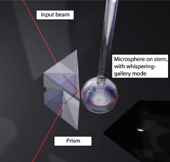
Whispering-gallery modes can support lasing in extremely small dielectric resonators. However, even glass spheres of roughly 1mm diameter - a macroscopically large size compared to the wavelength, - have long ago been observed to lase on such modes [C.G.B. Garrett et al., Phys. Rev. 124, p. 1807 (1961)]. In this large-size limit one can explore the interesting double limit ε→0 and λ/R→0. Here, ε is the deformation (in percent) away from the circular cross section, and λ is the wavelength, which should be compared to the mean cavity radius R. That is the point of view we pursue with a series of non-spherical resonators of mean radius R≈100μm. The index of refraction of such fused-silica spheroids is n=1.45, and in contrast to earlier experiments on lasing droplets they contain no amplifying dopants. |
|
The fused-silica material (glass) is shaped into a spheroid by melting the tip of a fiber. To create an asymmetric equatorial cross section, Scott Lacey melted two spheres together side by side. The resulting deformed object can be made more and more spherical, the longer it is heated up.
Compare the emission behavior of a near-spherical and a more deformed resonator in the two columns below. These are numerical calculations using a quasi-2D model assumption. In the experiment, the size parameters were different, and the deformations were studied in descending order. Here, on the other hand, we highlight the most striking new observation, made at the smallest deformations (left panel below):
 |
 |
|||||
|
|
|||||
 |
 |
How can emission patterns have fewer symmetries than the emitting cavity?The "pinwheel" shown above doesn't have reflection symmetry. This has arisen in another paper published shortly after the work described here, by Harayama et al. ["Asymmetric Stationary Lasing Patterns in 2D Symmetric Microcavities ", PRL 91, 073903 (2003)]. In my own work, this has previously happened in several different contexts: The basic idea is that all the symmetries of the cavity are indeed reflected in the quasibound states, but when some of these are nearly degenerate (to within their intrinsic linewidth) one can observe arbitrary superpositions that break some of the spatial symmetries. In our case, standing-waves of different parity under reflection combine into travelling waves. The travelling-wave superpositions whose wave patterns are plotted above are adapted to the experimental excitation conditions. I originally came up with this type of travelling-wave mode to explain the observed emission directionality in experiments by Claire Gmachl et al., in an earlier collaboration (unpublished). In lasers, such travelling waves can occur due to spontaneous symmetry breaking, and that caused me to use the same type of superpositions in modelling hexagonal zeolite-dye microlasers. The relationship between asymmetric emission, time-reversal and reflection symmetry was a main topic of my invited talk at the Symposium on semiclassical methods in atomic and molecular physics in Bonn, April 3, 2000. In the purely "elastic" experiments described here, the travelling waves are excited because the coupling prism injects waves with only one sense of circulation into the whispering-gallery region of the spheroid. There is more discussion of the difference between standing and traveling waves in open resonators on this page dealing with rotationally symmetric geometries. |
Note that the simulations show quasibound states of the isolated oval dielectric, in the absence of the prism. The most direct justification for this is that the observed directionality of similar resonances at a given deformation is in fact found to be independent of the prism location. I.e., the directionality is an intrinsic property of the cavity modes, essentially unmodified by weak tunnelling perturbations due to the input coupling. In a general scattering experiment at a sharp resonance, the far field is approximately the superposition of the input beam and the field of the resonant mode. In the experiment, the detector is placed in the half space opposite the prism, where there is negligible input beam intensity.
This page contains some additional material related to a collaboration at the Oregon Center for Optics, published in:
Scott Lacey, Hailin Wang, David H. Foster and Jens U.
Nöckel
Phys. Rev. Lett. 91, 033902 (2003)
See also the news page.
This page © Copyright Jens Uwe Nöckel, 10/2003
Last modified: Mon Mar 14 20:17:17 PDT 2011