
In micro- and nano-optics, bending losses are (next to scattering due to surface roughness) one of the most serious obstactles. When light propagates around bends in wave guides, it experiences the wave analogue of a centrifugal potential that causes leakage out of the guiding medium. In microspheres, microlasers and microrings, this sets the fundamental limit for the lifetime of resonant states. Even the seemingly mundane task of connecting a handful of optical devices becomes a logistical challenge when they are to be integrated on the same chip in close proximity to each other, simply because this can't be done without waveguide bends. The relative importance of bending losses grows as the wavelength of the light grows in relation to the bend radius. I.e., in the ray limit of zero wavelength, it is possible to ignore bending losses altogether.
Integrated photonic circuits could potentially be made even smaller if instead of confining light waves in dielectric (insulating) media, we could use surface plasmons at metal-dielectric interfaces. The reason is that surface plasmons are hybrid excitations in which the conduction electrons in the metal participate in the wave motion. This makes the wavelength of such waves shorter than it would be for light of the same frequency in the dielectric, and short effective wavelengths are desirable for miniaturization. However, the involvement of the conduction electrons also causes a severe drawback: unlike light in an insulator, surface plasmons experience absorption losses because some of their energy is drained by the resistance that affects moving charges in any realistic metal.
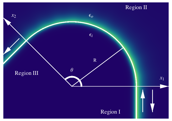 When surface plasmons go around a bend in a metal-dielectric interface, we now have two loss mechanisms that may be comparable: bending loss due to radiation into the dielectric, and absorption loss in the metal. We considered a two-dinensional model system in which we could quantitatively compare these competing effects by simulating the transmission coefficient of a surface plasmon wave. The wave is shown in false-color representation on the left. The region below the bend is metal, above it is air. The surface plasmon wave is incident from the bottom right, and its highest intensity is strongly concentrated near the interface between the metal and the air. The bend is called Region III, and the staight segments leading into and out of the bend are Regions I and II. Absorption losses lead to an exponential decay of the way along its propagation path, and readiation losses in region III lead to a long-tail falloff of the field in the radial direction away from the bend.
 The transmittance T has an upper bound determined by the least lossy way of getting around the bend. There are different "ways" of rounding the corner because there is a discontinuity at the connection points between the straight and bent surfaces. At these points, one can imagine a diffraction process taking place in which the incident wave splits into a range of curving wave patterns characterized by different values of an "angular momentum quantum number." The lowest possible of these angular momenta has the lowest losses, and the maximum transmittance is obtained by assuming that none of the incident energy is diffracted to other, more lossy channels (there is also reflection, as indicated by the bottom-right arrow).
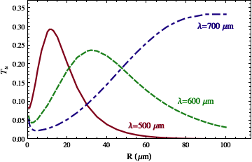
The surprising result of our analytical calculations within this approximation is revealed when comparing the bend transmittance with that of an equally long straight surface. Even though the bend adds a loss mechanism (bending loss through radiation), the upper limit for the transmittance can end up being lower than for a comparable straight segment. The plot on the right shows the upper bound for the transittivity as a function of the bend radius R, assuming a fixed bend angle θ = 90°. The red and green curves have a maximum, so that their transmittivity gets smaller for larger R. But larger R corresponds to the bend turning more gradually, and eventually becoming straight.
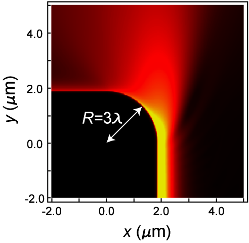 The reason for this phenomenon is that the angular momentum of the bending wave pushes it slightly out of the metal. This is just the "centrifugal force" that also causes radiation losses, but in the surface plasmon case it can be beneficial. Absorption in the metal is reduced when the wave is pushed out of the surface, even by a minute amount. The result is a larger net transmission despite the presence of radiation loss. For a very sharp bend whose radius R is just three times larger than the free-space wavelength λ, the numerical simulation on the left shows the combined effect of radiation and absorption losses for a ninety-degree bend.
An exact numerical simulation of the type shown here for R = 3 λ and λ = 630 nm is very hard to do for larger and larger R, but our analytical model (on which the first two figures are based) becomes more accurate precisely in this limit. The main purpose of the exact numerics is to validate the simplfying assumptions made in our approximate analytical calculation.
![]() The result of this check is shown in the last figure. Even though the bend radii are much smaller than what we assumed in the analytical approach, the predictions are still found to be qualitatively correct. The red dots are the exact numerical results, and the black line is the prediction corresponding to the analytical model (see the previous line graph). The overall transmittivity T is very low due to heavy radiation losses in this sharp bend, but T actually increases for sharper bends.
The result of this check is shown in the last figure. Even though the bend radii are much smaller than what we assumed in the analytical approach, the predictions are still found to be qualitatively correct. The red dots are the exact numerical results, and the black line is the prediction corresponding to the analytical model (see the previous line graph). The overall transmittivity T is very low due to heavy radiation losses in this sharp bend, but T actually increases for sharper bends.
This work is done in collaboration with graduate student Keisuke Hasegawa and his advisor, Miriam Deutsch. It was published in
This page © Copyright Jens Uwe Nöckel, 05/2011
Last modified: Sat Jun 4 17:55:21 PDT 2011


