Graphic Conventions
Please note that ADAAG maximums and minimums must be enforcaeable in project plans and spacifications. In many cases this will require indicating "maximum", "clear", or"minimum"on the plans.
Campus Planning & Real Estate
[] [] [] [] [] [][] [] [] [] [] [] [] [] [] [] [] [] [] [] [] [] [] [] [] [] [] [] [] [] [] [] [] [] [] []
Starting March 15, 2012, new federal ADA Standards for Accessible Design are in place and are available on the US Department of Justice and the US Access Board websites. As UO has not yet updated our guidance, design teams are to consult these new standards as well as the Oregonized ADAAG, which is based on the previous standard, for guidance on application of universal access principles in the use of federal accessibility standards.
Until our new written materials are in place, where conflicts occur between these two, please consult with Campus Planning & Real Estate staff, in particular Fred Tepfer or Cathy Soutar, for guidance.
[] [] [] [] [] [] [] [] [] [] [] [] [] [] [] [] [] [] [] [] [] [] [] [] [] [] [] [] [] [] [] [] [] [] [] []
This annotated version of the ATCTB's Americans with Disabilties Act Accessibility Guidelines is a work in progress, although it may be useful to you in its current unfinished state. For an unedited version of this document, consult the web site of the ATCTB (The Access Board) at http://www.access-board.gov.
Please note that text in green italic represents annotations related to work on the University of Oregon campus, which often are based on the principles of universal design. Annotations as OSSC: in bold underlined yellow are for coordination with OSSC, the Oregon state building code (a version of the Uniform Building Code). Annotations in dark blue preceded by UD: represent advice based on the principles of universal design. For more on this subject, refer to The Universal Design Handbook, McGraw-Hill, 2001. Links to explanations in the ADAAG appendix are indicated with A. Links to other explanatory information are shown as ?.
Please also note that this is a living document that will be updated periodically as ADAAG is modified and as experience adds to our knowledge base here on campus. It is best used in electronic form at this web site (darkwing.uoregeon.edu/~ftepfer/accessibility/adaag.htm/). You can review the current version history.
Please contact Fred Tepfer, (ftepfer@oregon.uoregon.edu) author of these annotations as well as much of the hyperlinking, with comments and questions, or use the input form linked from his home page at http://darkwing.uoregon.edu/~ftepfer/.
In future updates:
|
If you prefer a printer-friendly .pdf version of this
document, click here.
|
Sections 11 and 12 have not been incorporated in the Department of Justice accessibility standards and are, therefore, not enforceable.
This document sets guidelines for accessibility to places of public accommodation and commercial facilities by individuals with disabilities. These guidelines are to be applied during the design, construction, and alteration of such buildings and facilities to the extent required by regulations issued by Federal agencies, including the Department of Justice, under the Americans with Disabilities Act of 1990.
The illustrations and text of ANSI A117.1 are reproduced with permission from the American National Standards Institute. Copies of the standard may be purchased from the American National Standards Institute at 1430 Broadway, New York, New York 10018.
2.1 Provisions for Adults. The specifications in these
guidelines are based upon adult dimensions and anthropometrics.
See the Access Board or contact Planning for standards for children. These have
been approved by the Access Board but not yet adopted by U.S. Department of
Justice. Howver, UO is expects projects to use the Children's standard at a
minimum.
2.2* Equivalent Facilitation. Departures from particular
technical and scoping requirements of this guideline by the use of other designs
and technologies are permitted where the alternative designs and technologies
used will provide substantially equivalent or greater access to and usability
of the facility. A
Equivalent facilitation decisions are made in writing by the Campus Planning
Office in consultation with the Disabilities Issues Advisory Council (DIAC).
Projects seeking such a decision must have their design team apply in writing
to the University Planning Office.
3.1 Graphic Conventions. Graphic conventions are shown in Table 1. Dimensions that are not marked minimum or maximum are absolute, unless otherwise indicated in the text or captions.
Table 1
Graphic Conventions
Please note that ADAAG maximums and minimums must be enforcaeable
in project plans and spacifications. In many cases this will require indicating
"maximum", "clear", or"minimum"on the plans.
3.2 Dimensional Tolerances. All dimensions are subject to conventional building industry tolerances for field conditions. UO recommends that tolerances be incorporated in the project specifications.
3.3 Notes. The text of these guidelines does not contain notes or footnotes. Additional information, explanations, and advisory materials are located in the Appendix. Paragraphs marked with an asterisk have related, nonmandatory material in the Appendix. In the Appendix, the corresponding paragraph numbers are preceded by an A.
comply with. Meet one or more specifications of these guidelines.
if, if ... then. Denotes a specification that applies only when the conditions described are present.
may. Denotes an option or alternative.
shall. Denotes a mandatory specification or requirement.
should. Denotes an advisory specification or recommendation.
Addition. An expansion, extension, or increase in the gross floor area of a building or facility.
Administrative Authority. A governmental agency that adopts or enforces regulations and guidelines for the design, construction, or alteration of buildings and facilities.
Alteration. An alteration is a change to a building or facility made by, on behalf of, or for the use of a public accommodation or commercial facility, that affects or could affect the usability of the building or facility or part thereof. Alterations include, but are not limited to, remodeling, renovation, rehabilitation, reconstruction, historic restoration, changes or rearrangement of the structural parts or elements, and changes or rearrangement in the plan configuration of walls and full-height partitions. Normal maintenance, reroofing, painting or wallpapering, or changes to mechanical and electrical systems are not alterations unless they affect the usability of the building or facility. This normally includes all projects except for those limited to electrical or mechanical system improvements. UO includes as alterations projects those which modify or add office panel systems. Even electrical, mechanical, and finishes projects have an ADA dimension, as switches must be installed at accessible heights and if signs are painted over, they must be replaced with ADAAG-compliant signage
Area of Rescue Assistance. An area, which has direct access to an exit, where people who are unable to use stairs may remain temporarily in safety to await further instructions or assistance during emergency evacuation.
Assembly Area. A room or space accommodating a group of individuals for recreational, educational, political, social, or amusement purposes, or for the consumption of food and drink. UO uses the building code definition of an assembly area (room with an occupant load of 50 or more).
Automatic Door. A door equipped with a power-operated mechanism and controls that open and close the door automatically upon receipt of a momentary actuating signal. The switch that begins the automatic cycle may be a photoelectric device, floor mat, or manual switch (see power-assisted door).
Building. Any structure used and intended for supporting or sheltering any use or occupancy.
Circulation Path. An exterior or interior way of passage from one place to another for pedestrians, including, but not limited to, walks, hallways, courtyards, stairways, and stair landings.
Clear. Unobstructed. And should generally be dimensioned as "clear" or as "minimum".
Clear Floor Space. The minimum unobstructed floor or ground space required to accommodate a single, stationary wheelchair and occupant.
Closed Circuit Telephone. A telephone with dedicated line(s) such as a house phone, courtesy phone or phone that must be used to gain entrance to a facility.
Common Use. Refers to those interior and exterior rooms, spaces, or elements that are made available for the use of a restricted group of people (for example, occupants of a homeless shelter, the occupants of an office building, or the guests of such occupants).
Cross Slope. The slope that is perpendicular to the direction of travel (see running slope).
Curb Ramp. A short ramp cutting through a curb or built up to it.
Detectable Warning. A standardized surface feature built in or applied to walking surfaces or other elements to warn visually impaired people of hazards on a circulation path.
DIAC, Disbility Issues Advisory Council. The UO committee that advises administrative determinations on accessibility issues.
Dwelling Unit. A single unit which provides a kitchen or food preparation area, in addition to rooms and spaces for living, bathing, sleeping, and the like. Dwelling units include a single family home or a townhouse used as a transient group home; an apartment building used as a shelter; guestrooms in a hotel that provide sleeping accommodations and food preparation areas; and other similar facilities used on a transient basis. For purposes of these guidelines, use of the term "Dwelling Unit" does not imply the unit is used as a residence.
Egress, Means of. A continuous and unobstructed way of exit travel from any point in a building or facility to a public way. A means of egress comprises vertical and horizontal travel and may include intervening room spaces, doorways, hallways, corridors, passageways, balconies, ramps, stairs, enclosures, lobbies, horizontal exits, courts and yards. An accessible means of egress is one that complies with these guidelines and does not include stairs, steps, or escalators. Areas of rescue assistance or evacuation elevators may be included as part of accessible means of egress.
Element. An architectural or mechanical component of a building, facility, space, or site, e.g., telephone, curb ramp, door, drinking fountain, seating, or water closet.
Entrance. Any access point to a building or portion of a building or facility used for the purpose of entering. An entrance includes the approach walk, the vertical access leading to the entrance platform, the entrance platform itself, vestibules if provided, the entry door(s) or gate(s), and the hardware of the entry door(s) or gate(s).
Facility. All or any portion of buildings, structures, site improvements, complexes, equipment, roads, walks, passageways, parking lots, or other real or personal property located on a site.
Ground Floor. Any occupiable floor less than one story above or below grade with direct access to grade. A building or facility always has at least one ground floor and may have more than one ground floor as where a split level entrance has been provided or where a building is built into a hillside.
Mezzanine or Mezzanine Floor. That portion of a story which is an intermediate floor level placed within the story and having occupiable space above and below its floor.
Marked Crossing. A crosswalk or other identified path intended for pedestrian use in crossing a vehicular way.
Multifamily Dwelling. Any building containing more than two dwelling units.
Occupiable. A room or enclosed space designed for human occupancy in which individuals congregate for amusement, educational or similar purposes, or in which occupants are engaged at labor, and which is equipped with means of egress, light, and ventilation.
Operable Part. A part of a piece of equipment or appliance used to insert or withdraw objects, or to activate, deactivate, or adjust the equipment or appliance (for example, coin slot, pushbutton, handle).
Path of Travel. (Reserved).
PAC, Physical Access Committee. The UO advisory committee for physical barriers.
Power-assisted Door. A door used for human passage with a mechanism that helps to open the door, or relieves the opening resistance of a door, upon the activation of a switch or a continued force applied to the door itself.
Public Use. Describes interior or exterior rooms or spaces that are made available to the general public. Public use may be provided at a building or facility that is privately or publicly owned.
Ramp. A walking surface which has a running slope greater than 1:20.
Running Slope. The slope that is parallel to the direction of travel (see cross slope).
Service Entrance. An entrance intended primarily for delivery of goods or services.
Signage. Displayed verbal, symbolic, tactile, and pictorial information.
Site. A parcel of land bounded by a property line or a designated portion of a public right-of-way.
Site Improvement. Landscaping, paving for pedestrian and vehicular ways, outdoor lighting, recreational facilities, and the like, added to a site.
Sleeping Accommodations. Rooms in which people sleep; for example, dormitory and hotel or motel guest rooms or suites. UO Residence Halls fit within this category. Apartments and houses do not, and are not currently covered under ADAAG. The Uniform Federal Accessibility Guidelines (UFAS) should be used instead.
Space. A definable area, e.g., room, toilet room, hall, assembly area, entrance, storage room, alcove, courtyard, or lobby.
Story. That portion of a building included between the upper surface of a floor and upper surface of the floor or roof next above. If such portion of a building does not include occupiable space, it is not considered a story for purposes of these guidelines. There may be more than one floor level within a story as in the case of a mezzanine or mezzanines.
Structural Frame. The structural frame shall be considered to be the columns and the girders, beams, trusses and spandrels having direct connections to the columns and all other members which are essential to the stability of the building as a whole.
Tactile. Describes an object that can be perceived using the sense of touch.
Text Telephone. Machinery or equipment that employs interactive graphic (i.e., typed) communications through the transmission of coded signals across the standard telephone network. Text telephones can include, for example, devices known as TDD's (telecommunication display devices or telecommunication devices for deaf persons) or computers.
Transient Lodging. A building, facility, or portion thereof, excluding inpatient medical care facilities, that contains one or more dwelling units or sleeping accommodations. Transient lodging may include, but is not limited to, resorts, group homes, hotels, motels, and dormitories. UO Residence Halls fit within this category.
Vehicular Way. A route intended for vehicular traffic, such as a street, driveway, or parking lot.
Walk. An exterior pathway with a prepared surface intended for pedestrian use, including general pedestrian areas such as plazas and courts.
(1) General. All areas of newly designed or newly constructed buildings and facilities required to be accessible by 4.1.2 and 4.1.3 and altered portions of existing buildings and facilities required to be accessible by 4.1.6 shall comply with these guidelines, 4.1 through 4.35, unless otherwise provided in this section or as modified in a special application section.(2) Application Based on Building Use. Special application sections 5 through 10 provide additional requirements for restaurants and cafeterias, medical care facilities, business and mercantile, libraries, accessible transient lodging, and transportation facilities. When a building or facility contains more than one use covered by a special application section, each portion shall comply with the requirements for that use.
(3)* Areas Used Only by Employees as Work Areas. Areas that are used only as work areas shall be designed and constructed so that individuals with disabilities can approach, enter, and exit the areas. These guidelines do not require that any areas used only as work areas be constructed to permit maneuvering within the work area or be constructed or equipped (i.e., with racks or shelves) to be accessible. A
This section generally does not apply to the University of Oregon except that free-standing furniture in employee work areas need not be accessible, although reasonable provisions for adaptability are recommended. In all facilities serving students and/or the public, this exception does not apply. It is sometimes used in work areas in kitchens and research laboratories where functional or equipment needs are in conflict with ADAAG. Consult UO Planning before using this section.(4) Temporary Structures. These guidelines cover temporary buildings or facilities as well as permanent facilities. Temporary buildings and facilities are not of permanent construction but are extensively used or are essential for public use for a period of time. Examples of temporary buildings or facilities covered by these guidelines include, but are not limited to: reviewing stands, temporary classrooms, bleacher areas, exhibit areas, temporary banking facilities, temporary health screening services, or temporary safe pedestrian passageways around a construction site. Structures, sites and equipment directly associated with the actual processes of construction, such as scaffolding, bridging, materials hoists, or construction trailers are not included.
(a) In new construction, a person or entity is not required to meet fully the requirements of these guidelines where that person or entity can demonstrate that it is structurally impracticable to do so. Full compliance will be considered structurally impracticable only in those rare circumstances when the unique characteristics of terrain prevent the incorporation of accessibility features. If full compliance with the requirements of these guidelines is structurally impracticable, a person or entity shall comply with the requirements to the extent it is not structurally impracticable. Any portion of the building or facility which can be made accessible shall comply to the extent that it is not structurally impracticable. Cases for structural impractibililty must be made in writing by the project design team to the University Planning Office. All such determinations will be made in writing and kept in the building's ADA files(b) Accessibility is not required to (i) observation galleries used primarily for security purposes; or (ii) in non-occupiable spaces accessed only by ladders, catwalks, crawl spaces, very narrow passageways, or freight (non-passenger) elevators, and frequented only by service personnel for repair purposes; such spaces include, but are not limited to, elevator pits, elevator penthouses, piping or equipment catwalks.
4.1.2 Accessible Sites and Exterior Facilities: New Construction. An accessible site shall meet the following minimum requirements:
(1) At least one accessible route complying with 4.3 shall be provided within the boundary of the site from public transportation stops, accessible parking spaces, passenger loading zones if provided, and public streets or sidewalks, to an accessible building entrance. In keeping with the UO endorsement of the principles of universal design, UO makes all exterior routes accessible except where this is not possible. In practice, this means that where barriers such as stairs are part of the site design, an equally direct parallel route is clearly visible if possible.(2) At least one accessible route complying with 4.3 shall connect accessible buildings, accessible facilities, accessible elements, and accessible spaces that are on the same site. In keeping with the UO endorsement of the principles of universal design, UO makes all exterior routes accessible except where this is not possible. In practice, this means that where barriers exist, an equally direct parallel route is clearly visible.
(3) All objects that protrude from surfaces or posts into circulation paths shall comply with 4.4.
(4) Ground surfaces along accessible routes and in accessible spaces shall comply with 4.5.
(5) (a) If parking spaces are provided for self-parking by employees or visitors, or both, then accessible spaces complying with 4.6 shall be provided in each such parking area in conformance with the table below. Spaces required by the table need not be provided in the particular lot. They may be provided in a different location if equivalent or greater accessibility, in terms of distance from an accessible entrance, cost and convenience is ensured. Under the equivalent facilitation provisions of ADAAG, the UO accommodates employees on an individual basis. Please contact Campus Planning for advice when designing parking facilities.
OSSC: Please note that Oregon requirements for accessible parking stalls are more stringent than ADAAG. Parking stall minimum width is 9 feet, for example, rather than 8 feet, and pole-mounted signs are required to be high.
Total Parking in Lot Required Minimum Number of Accessible Spaces Except as provided in (b), access aisles adjacent to accessible spaces shall be 60 in (1525 mm) wide minimum. Many designers are not fully aware of the degree of hazard nor the requirements for proximity and accessible route to the entrance. UO generally does not accept striped paving as an accessible route in a parking lot except to cross driveways. UO assumes that such crossings will be designed to be as short as possible, as they represent a potential user hazard. All transitions between pedestrian areas and vehicular areas should be protected by curbs or by 36" of tactile paving.
- (b) One in every eight accessible spaces, but not less than one, shall be served by an access aisle 96 in (2440 mm) wide minimum and shall be designated "van accessible" as required by 4.6.4. The vertical clearance at such spaces shall comply with 4.6.5. All such spaces may be grouped on one level of a parking structure.
- EXCEPTION: Provision of all required parking spaces in conformance with "Universal Parking Design" (see appendix A4.6.3) is permitted.
- Oregon State Law now also requires these spaces in some cases to be identified as wheelchair users spaces.
- (c) If passenger loading zones are provided, then at least one passenger loading zone shall comply with 4.6.6.
(d) At facilities providing medical care and other services for persons with mobility impairments, parking spaces complying with 4.6 shall be provided in accordance with 4.1.2(5)(a) except as follows:
(i) Outpatient units and facilities: 10 percent of the total number of parking spaces provided serving each such outpatient unit or facility;(ii) Units and facilities that specialize in treatment or services for persons with mobility impairments: 20 percent of the total number of parking spaces provided serving each such unit or facility.
(e)* Valet parking: Valet parking facilities shall provide a passenger loading zone complying with 4.6.6 located on an accessible route to the entrance of the facility. Paragraphs 5(a), 5(b), and 5(d) of this section do not apply to valet parking facilities.
- (6) If toilet facilities are provided on a site, then each such public or common use toilet facility shall comply with 4.22. If bathing facilities are provided on a site, then each such public or common use bathing facility shall comply with 4.23. For single user portable toilet or bathing units clustered at a single location, at least 5% but no less than one toilet unit or bathing unit complying with 4.22 or 4.23 shall be installed at each cluster whenever typical inaccessible units are provided. Accessible units shall be identified by the International Symbol of Accessibility.
- EXCEPTION: Portable toilet units at construction sites used exclusively by construction personnel are not required to comply with 4.1.2(6).
- Note that many accessible portable toilets do not comply with the requirements for landings at doors. Please make sure that temporary landings are provided if needed.
(7) Building Signage. Signs which designate permanent rooms and spaces shall comply with 4.30.1, 4.30.4, 4.30.5 and 4.30.6. Other signs which provide direction to, or information about, functional spaces of the building shall comply with 4.30.1, 4.30.2, 4.30.3, and 4.30.5. Elements and spaces of accessible facilities which shall be identified by the International Symbol of Accessibility and which shall comply with 4.30.7 are:
(a) Parking spaces designated as reserved for individuals with disabilities;(b) Accessible passenger loading zones;
(c) Accessible entrances when not all are accessible (inaccessible entrances shall have directional signage to indicate the route to the nearest accessible entrance);
(d) Accessible toilet and bathing facilities when not all are accessible.
4.1.3 Accessible Buildings: New Construction. Accessible buildings and facilities shall meet the following minimum requirements:
(1) At least one accessible route complying with 4.3 shall connect accessible building or facility entrances with all accessible spaces and elements within the building or facility. In keeping with the UO endorsement of the principal of universal design, UO generally designs all routes to be accessible.
(2) All objects that overhang or protrude into circulation paths shall comply with 4.4.
(3) Ground and floor surfaces along accessible routes and in accessible rooms and spaces shall comply with 4.5.
(4) Interior and exterior stairs connecting levels that are not connected by an elevator, ramp, or other accessible means of vertical access shall comply with 4.9.
(5)* One passenger elevator complying with 4.10 shall serve each level, including mezzanines, in all multi-story buildings and facilities unless exempted below. If more than one elevator is provided, each full passenger elevator shall comply with 4.10.
EXCEPTION 1: This exception does not apply to the UO, an ADATitle II entity. Elevators are not required in facilities that are less than three stories or that have less than 3000 square feet per story unless the building is a shopping center, a shopping mall, or the professional office of a health care provider, or another type of facility as determined by the Attorney General. The elevator exemption set forth in this paragraph does not obviate or limit in any way the obligation to comply with the other accessibility requirements established in section 4.1.3. For example, floors above or below the accessible ground floor must meet the requirements of this section except for elevator service. If toilet or bathing facilities are provided on a level not served by an elevator, then toilet or bathing facilities must be provided on the accessible ground floor. In new construction if a building or facility is eligible for this exemption but a full passenger elevator is nonetheless planned, that elevator shall meet the requirements of 4.10 and shall serve each level in the building. A full passenger elevator that provides service from a garage to only one level of a building or facility is not required to serve other levels.
EXCEPTION 2: Elevator pits, elevator penthouses, mechanical rooms, piping or equipment catwalks are exempted from this requirement.
EXCEPTION 3: Accessible ramps complying with 4.8 may be used in lieu of an elevator. UO discourages the use of ramps to connect levels that are separated by five feet or more in vertical dimension.
EXCEPTION 4: Platform lifts (wheelchair lifts) complying with 4.11 of this guideline and applicable state or local codes may be used in lieu of an elevator only under the following conditions: Use of this provision is strongly discouraged, and must be approved in advance by Campus Planning.
(a) To provide an accessible route to a performing area in an assembly occupancy.(b) To comply with the wheelchair viewing position line-of- sight and dispersion requirements of 4.33.3.
(c) To provide access to incidental occupiable spaces and rooms which are not open to the general public and which house no more than five persons, including but not limited to equipment control rooms and projection booths.
(d) To provide access where existing site constraints or other constraints make use of a ramp or an elevator infeasible.
(6) Windows: (Reserved).
(a) At each accessible entrance to a building or facility, at least one door shall comply with 4.13.(b) Within a building or facility, at least one door at each accessible space shall comply with 4.13. UD: All doors should be made accessible.
(c) Each door that is an element of an accessible route shall comply with 4.13.
(d) Each door required by 4.3.10, Egress, shall comply with 4.13.
(8) In new construction, at a minimum, the requirements in (a) and (b) below shall be satisfied independently:
(a)(i) At least 50% of all public entrances (excluding those in (b) below) must be accessible. At least one must be a ground floor entrance. Public entrances are any entrances that are not loading or service entrances. UO strives to make all public entrances accessible in new construction and major renovations. We also require a power operated door at at least one primary entrance in new buildings or in major remodel projects. Please contact Campus Planning if this goal can not be met. See diagram for information on power door operator location. Power door actuator buttons or touchpads should be installed at +42" to coordinate with elevator call button heights and to best serve populations with the greatest physical impairments such as quadraplegics.(ii) Accessible entrances must be provided in a number at least equivalent to the number of exits required by the applicable building/fire codes. (This paragraph does not require an increase in the total number of entrances planned for a facility.)
(iii) An accessible entrance must be provided to each tenancy in a facility (for example, individual stores in a strip shopping center).
One entrance may be considered as meeting more than one of the requirements in (a). Where feasible, accessible entrances shall be the entrances used by the majority of people visiting or working in the building. Exceptions to this principle must be approved by Campus Planning.
(b)(i) In addition, if direct access is provided for pedestrians from an enclosed parking garage to the building, at least one direct entrance from the garage to the building must be accessible. Accessible parking must be provided at all levels connecting directly from parking to building.
(ii) If access is provided for pedestrians from a pedestrian tunnel or elevated walkway, one entrance to the building from each tunnel or walkway must be accessible. UD: All entrances and walkways should be made accessible.
One entrance may be considered as meeting more than one of the requirements in (b).
Because entrances also serve as emergency exits whose proximity to all parts of buildings and facilities is essential, it is preferable that all entrances be accessible.
(c) If the only entrance to a building, or tenancy in a facil
ity, is a service entrance, that entrance shall be accessible.
(d) Entrances which are not accessible shall have directional signage complying with 4.30.1, 4.30.2, 4.30.3, and 4.30.5, which indicates the location of the nearest accessible entrance.
- (9)* In buildings or facilities, or portions of buildings or facilities, required to be accessible, accessible means of egress shall be provided in the same number as required for exits by local building/life safety regulations. Where a required exit from an occupiable level above or below a level of accessible exit discharge is not accessible, an area of rescue assistance shall be provided on each such level (in a number equal to that of inaccessible required exits). Areas of rescue assistance shall comply with 4.3.11. A horizontal exit, meeting the requirements of local building/life safety regulations, shall satisfy the requirement for an area of rescue assistance.
- EXCEPTION: Areas of rescue assistance are not required in buildings or facilities having a supervised automatic sprinkler system.
- UO prefers sprinklered buildings over areas of rescue assistance.
(a) Where only one drinking fountain is provided on a floor there shall be a drinking fountain which is accessible to individuals who use wheelchairs in accordance with 4.15 and one accessible to those who have difficulty bending or stooping. (This can be accommodated by the use of a "hi-lo" fountain; by providing one fountain accessible to those who use wheelchairs and one fountain at a standard height convenient for those who have difficulty bending; by providing a fountain accessible under 4.15 and a water cooler; or by such other means as would achieve the required accessibility for each group on each floor.) A
Ensure that fountains don't become protrusion hazards (see ADAAG 4.4). [EXAMPLE](b) Where more than one drinking fountain or water cooler is provided on a floor, 50% of those provided shall comply with 4.15 and shall be on an accessible route.
(11) Toilet Facilities: If toilet rooms are provided, then each public and common use toilet room shall comply with 4.22. Other toilet rooms provided for the use of occupants of specific spaces (i.e., a private toilet room for the occupant of a private office) shall be adaptable. Use of this provision requires consultation with University Planning. If bathing rooms are provided, then each public and common use bathroom shall comply with 4.23. Accessible toilet rooms and bathing facilities shall be on an accessible route. Where bathing facilities are provided and in larger facilities, a certain number of single occupant uni-sex facilities are desirable to allow for attendants of the opposite sex. OSSC: This may be required.
(12) Storage, Shelving and Display Units:
(a) If fixed or built-in storage facilities such as cabinets, shelves, closets, and drawers are provided in accessible spaces, at least one of each type provided shall contain storage space complying with 4.25. Additional storage may be provided outside of the dimensions required by 4.25. Ensure that the storage is functional for people with disabilities: within the reach ranges, not blocked by typical mobility aids such as wheechair chairs and walkers, etc. This provision also applies to departmental mailboxes, lockers, and similar installations.(b) Shelves or display units allowing self-service by customers in mercantile occupancies shall be located on an accessible route complying with 4.3. Requirements for accessible reach range do not apply. If self-service above accessible reach ranges is provided, a prominent sign offering assistance must be provided at the entrance and/or at the checkout area.
(13) Controls and operating mechanisms in accessible spaces, along accessible routes, or as parts of accessible elements (for example, light switches and dispenser controls) shall comply with 4.27. This applies to ALL features that users have access to, which may include soda dispensers, thermostats, lecterns, circuit breakers, etc.
(14) If emergency warning systems are provided, then they shall include both audible alarms and visual alarms complying with 4.28. Sleeping accommodations required to comply with 9.3 shall have an alarm system complying with 4.28. Emergency warning systems in medical care facilities may be modified to suit standard health care alarm design practice. When designing alarms, allow future capacity so that UO can provide alarms in individual offices, sleeping rooms, etc. to accommodate specific individuals in the future.
(15) Detectable warnings shall be provided at locations as specified in 4.29. UO strongly recommends this element at transitions from pedestrian areas to vehicular areas which are flat (not curbed) to provide warning for low-vision and blind individuals. [link forthcoming]
(a) Signs which designate permanent rooms and spaces shall comply with 4.30.1, 4.30.4, 4.30.5 and 4.30.6. These need to have raised letters and Braille. UO interprets "permanent designation" to include lecture halls, kitchens, etc.
- (b) Other signs which provide direction to or information about functional spaces of the building shall comply with 4.30.1, 4.30.2, 4.30.3, and 4.30.5.
- EXCEPTION: Building directories, menus, and all other signs which are temporary are not required to comply.
- Note: UO strives to make all signage relatively accessible. Please pay attention to typefaces, sizes, and locations when designing within this exception. Advice is available from Campus Planning.
(a) If public pay telephones, public closed circuit telephones, or other public telephones are provided, then they shall comply with 4.31.2 through 4.31.8 to the extent required by the following table:
Number of each type of telephone provided on each floor Number of telephones required to comply with 4.31.2 through 4.31.8 1 or more single unit 1 per floor 1 bank 1 per floor 2 or more banks 1 per bank. Accessible unit unit may be installed as a single unit in proximity (either visible or with signage) to the bank. At least one public telephone per floor shall meet the requirements for a forward reach telephone. 1 Additional public telephones may be installed at any height. Unless otherwise specified, accessible telephones may be either forward or side reach telephones. UO standard is to use the forward reach range only for new telephone installations.
2 A bank consists of two or more adjacent public telephones, often installed as a unit.
3 EXCEPTION: For exterior installations only, if dial tone first service is available, then a side reach telephone may be installed instead of the required forward reach telephone (i.e., one telephone in proximity to each bank shall comply with 4.31).
(b)* All telephones required to be accessible and complying with 4.31.2 through 4.31.8 shall be equipped with a volume control. In addition, 25 percent, but never less than one, of all other public telephones provided shall be equipped with a volume control and shall be dispersed among all types of public telephones, including closed circuit telephones, throughout the building or facility. Signage complying with applicable provisions of 4.30.7 shall be provided.
(c) The following shall be provided in accordance with 4.31.9:
(i) if a total number of four or more public pay telephones (including both interior and exterior phones) is provided at a site, and at least one is in an interior location, then at least one interior public text telephone shall be provided.(ii) if an interior public pay telephone is provided in a stadium or arena, in a convention center, in a hotel with a convention center, or in a covered mall, at least one interior public text telephone shall be provided in the facility.
(iii) if a public pay telephone is located in or adjacent to a hospital emergency room, hospital recovery room, or hospital waiting room, one public text telephone shall be provided at each such location.
(d) Where a bank of telephones in the interior of a building consists of three or more public pay telephones, at least one public pay telephone in each such bank shall be equipped with a shelf and outlet in compliance with 4.31.9(2).
(18) If fixed or built-in seating or tables (including, but not limited to, study carrels and student laboratory stations), are provided in accessible public or common use areas, at least five percent (5%), but not less than one, of the fixed or built-in seating areas or tables shall comply with 4.32. An accessible route shall lead to and through such fixed or built-in seating areas, or tables. UO standard for accessible seating includes provisions for vertical adjustment of writing/work surfaces in a reasonable number of locations. Contact Campus Planning for details.
(a) In places of assembly with fixed seating accessible wheelchair locations shall comply with 4.33.2, 4.33.3, and 4.33.4 and shall be provided consistent with the following table:
Capacity of Seating in Assembly Areas Number of Required Wheelchair Locations 4 to 25 1 26 to 50 2 51 to 300 3 301 to 500 4 over 500 6, plus 1 additional space for each total seating capacity increase of 100 In addition, one percent, but not less than one, of all fixed seats shall be aisle seats with no armrests on the aisle side, or removable or folding armrests on the aisle side. Each such seat shall be identified by a sign or marker. Signage notifying patrons of the availability of such seats shall be posted at the ticket office. Aisle seats are not required to comply with 4.33.4. Also see UO standards for classroom accessibility. (coming soon)
(b) This paragraph applies to assembly areas where audible communications are integral to the use of the space (e.g., concert and lecture halls, playhouses and movie theaters, meeting rooms, etc.). Such assembly areas, if (1) they accommodate at least 50 persons, or if they have audio-amplification systems, and (2) they have fixed seating, shall have a permanently installed assistive listening system complying with 4.33. For other assembly areas, a permanently installed assistive listening system, or an adequate number of electrical outlets or other supplementary wiring necessary to support a portable assistive listening system shall be provided. The minimum number of receivers to be provided shall be equal to 4 percent of the total number of seats, but in no case less than two. Signage complying with applicable provisions of 4.30 shall be installed to notify patrons of the availability of a listening system. UO uses an FM wireless system as its standard in classrooms and most other assembly areas. Contact Campus Planning for information about compatibility with our standard.
- (20) Where automated teller machines (ATMs) are provided, each ATM shall comply with the requirements of 4.34 except where two or more are provided at a location, then only one must comply.
- EXCEPTION: Drive-up-only automated teller machines are not required to comply with 4.27.2, 4.27.3 and 4.34.3.
(21) Where dressing and fitting rooms are provided for use by the general public, patients, customers or employees, 5 percent, but never less than one, of dressing rooms for each type of use in each cluster of dressing rooms shall be accessible and shall comply with 4.35.
Examples of types of dressing rooms are those serving different genders or distinct and different functions as in different treatment or examination facilities.
4.1.5 Accessible Buildings: Additions. Each addition to an existing building or facility shall be regarded as an alteration. Each space or element added to the existing building or facility shall comply with the applicable provisions of 4.1.1 to 4.1.3, Minimum Requirements (for New Construction) and the applicable technical specifications of 4.2 through 4.35 and sections 5 through 10. Each addition that affects or could affect the usability of an area containing a primary function shall comply with 4.1.6(2).
4.1.6 Accessible Buildings: Alterations.
(1) General. Alterations to existing buildings and facilities shall comply with the following:(a) No alteration shall be undertaken which decreases or has the effect of decreasing accessibility or usability of a building or facility below the requirements for new construction at the time of alteration.(b) If existing elements, spaces, or common areas are altered, then each such altered element, space, feature, or area shall comply with the applicable provisions of 4.1.1 to 4.1.3 Minimum Requirements (for New Construction). If the applicable provision for new construction requires that an element, space, or common area be on an accessible route, the altered element, space, or common area is not required to be on an accessible route except as provided in 4.1.6(2) (Alterations to an Area Containing a Primary Function.)
(c) If alterations of single elements, when considered together, amount to an alteration of a room or space in a building or facility, the entire space shall be made accessible.
(d) No alteration of an existing element, space, or area of a building or facility shall impose a requirement for greater accessibility than that which would be required for new construction. For example, if the elevators and stairs in a building are being altered and the elevators are, in turn, being made accessible, then no accessibility modifications are required to the stairs connecting levels connected by the elevator. If stair modifications to correct unsafe conditions are required by other codes, the modifications shall be done in compliance with these guidelines unless technically infeasible.
(e) At least one interior public text telephone complying with 4.31.9 shall be provided if:
(i) alterations to existing buildings or facilities with less than four exterior or interior public pay telephones would increase the total number to four or more telephones with at least one in an interior location; or(ii) alterations to one or more exterior or interior public pay telephones occur in an existing building or facility with four or more public telephones with at least one in an interior location.
(f) If an escalator or stair is planned or installed where none existed previously and major structural modifications are necessary for such installation, then a means of accessible vertical access shall be provided that complies with the applicable provisions of 4.7, 4.8, 4.10, or 4.11.
(g) In alterations, the requirements of 4.1.3(9), 4.3.10 and 4.3.11 do not apply. These are the requirements for egress and rescue assistance. However, UO standard is to consider this issue in large alteration projects, although possibly not to the level required in new construction. Alterations of buildings which are not fire sprinklered may be required to provide horizontal exits or areas of rescue assistance.
(h)* Entrances: If a planned alteration entails alterations to an entrance, and the building has an accessible entrance, the entrance being altered is not required to comply with 4.1.3(8), except to the extent required by 4.1.6(2). If a particular entrance is not made accessible, appropriate accessible signage indicating the location of the nearest accessible entrance(s) shall be installed at or near the inaccessible entrance, such that a person with disabilities will not be required to retrace the approach route from the inaccessible entrance. UO requires that when an entrance is being altered, either it will be made accessible or Campus Planning and the designers must determine that it is not feasible or necessary to make it accessible.
(i) If the alteration work is limited solely to the electrical, mechanical, or plumbing system, or to hazardous material abatement, or automatic sprinkler retrofitting, and does not involve the alteration of any elements or spaces required to be accessible under these guidelines, then 4.1.6(2) (which are the requirements for barrier removal on the path of travel to the alteration site) does not apply.
(j) EXCEPTION: In alteration work, if compliance with 4.1.6 is technically infeasible, the alteration shall provide accessibility to the maximum extent feasible. Any elements or features of the building or facility that are being altered and can be made accessible shall be made accessible within the scope of the alteration. Determinations of technical infeasibility are made by the University Planning Office in consultation with DIAC and PAC.
Technically Infeasible. Means, with respect to an alteration of a building or a facility, that it has little likelihood of being accomplished because existing structural conditions would require removing or altering a load-bearing member which is an essential part of the structural frame; or because other existing physical or site constraints prohibit modification or addition of elements, spaces, or features which are in full and strict compliance with the minimum requirements for new construction and which are necessary to provide accessibility.
(i) These guidelines do not require the installation of an elevator in an altered facility that is less than three stories or has less than 3,000 square feet per story unless the building is a shopping center, a shopping mall, the professional office of a health care provider, or another type of facility as determined by the Attorney General. This exception does not apply to ADA Title II entities such as the UO.(ii) The exemption provided in paragraph (i) does not obviate or limit in any way the obligation to comply with the other accessibility requirements established in these guidelines. For example, alterations to floors above or below the ground floor must be accessible regardless of whether the altered facility has an elevator. If a facility subject to the elevator exemption set forth in paragraph (i) nonetheless has a full passenger elevator, that elevator shall meet, to the maximum extent feasible, the accessibility requirements of these guidelines.
(2) Alterations to an Area Containing a Primary Function: In addition to the requirements of 4.1.6(1), an alteration that affects or could affect the usability of or access to an area containing a primary function shall be made so as to ensure that, to the maximum extent feasible, the path of travel to the altered area and the restrooms, telephones, and drinking fountains serving the altered area, are readily accessible to and usable by individuals with disabilities, unless such alterations are disproportionate to the overall alterations in terms of cost and scope (as determined under criteria established by the Attorney General). UO requires that the designer of an alteration project make this analysis and provide a copy to Campus Planning. Because the requirements of Oregon State Law (ORS 447.241) are similar but slightly more stringent, UO uses the provisions of this section with 25% as the threshold of what is disproportionate, consistent with ORS 447.241.
OSSC: To see ORS 447.241, click here.
(3) Special Technical Provisions for Alterations to Existing Buildings and Facilities:
(a) Ramps: Curb ramps and interior or exterior ramps to be constructed on sites or in existing buildings or facilities where space limitations prohibit the use of a 1:12 slope or less may have slopes and rises as follows:(i) A slope between 1:10 and 1:12 is allowed for a maximum rise of 6 inches.(ii) A slope between 1:8 and 1:10 is allowed for a maximum rise of 3 inches. A slope steeper than 1:8 is not allowed.
(b) Stairs: Full extension of handrails at stairs shall not be required in alterations where such extensions would be hazardous or impossible due to plan configuration.
(i) If safety door edges are provided in existing automatic elevators, automatic door reopening devices may be omitted (see 4.10.6).(ii) Where existing shaft configuration or technical infeasibility prohibits strict compliance with 4.10.9, the minimum car plan dimensions may be reduced by the minimum amount necessary, but in no case shall the inside car area be smaller than 48 in by 48 in. Use this provision only with the approval of Universtiy Planning.
(iii) Equivalent facilitation may be provided with an elevator car of different dimensions when usability can be demonstrated and when all other elements required to be accessible comply with the applicable provisions of 4.10. For example, an elevator of 47 in by 69 in (1195 mm by 1755 mm) with a door opening on the narrow dimension, could accommodate the standard wheelchair clearances shown in Figure 4. Use this provision only with the approval of University Planning.
(i) Where it is technically infeasible to comply with clear opening width requirements of 4.13.5, a projection of 5/8 in maximum will be permitted for the latch side stop.(ii) If existing thresholds are 3/4 in high or less, and have (or are modified to have) a beveled edge on each side, they may remain.
(i) Where it is technically infeasible to comply with 4.22 or 4.23, the installation of at least one unisex toilet/bathroom per floor, located in the same area as existing toilet facilities, will be permitted in lieu of modifying existing toilet facilities to be accessible. Each unisex toilet room shall contain one water closet complying with 4.16 and one lavatory complying with 4.19, and the door shall have a privacy latch. In some situations UO encourages the use of this provision in order to provide facilities for people with attendants of the opposite sex.(ii) Where it is technically infeasible to install a required standard stall (Fig. 30(a)), or where other codes prohibit reduction of the fixture count (i.e., removal of a water closet in order to create a double-wide stall), either alternate stall (Fig.30(b)) may be provided in lieu of the standard stall. UO strongly discourages use of this provision and requires advance approval.
(iii) When existing toilet or bathing facilities are being altered and are not made accessible, signage complying with 4.30.1, 4.30.2, 4.30.3, 4.30.5, and 4.30.7 shall be provided indicating the location of the nearest accessible toilet or bathing facility within the facility. In major remodels, UO may require this signage at restrooms which have not been made accessible.
(i) Where it is technically infeasible to disperse accessible seating throughout an altered assembly area, accessible seating areas may be clustered. Each accessible seating area shall have provisions for companion seating and shall be located on an accessible route that also serves as a means of emergency egress. Use this provision only with the approval of University Planning. See UO standards for classroom accessibility.(ii) Where it is technically infeasible to alter all performing areas to be on an accessible route, at least one of each type of performing area shall be made accessible. Use this provision only with the approval of Universtiy Planning.
(g) Platform Lifts (Wheelchair Lifts): In alterations, platform lifts (wheelchair lifts) complying with 4.11 and applicable state or local codes may be used as part of an accessible route. The use of lifts is not limited to the four conditions in exception 4 of 4.1.3(5) UO seldom allows lifts. Use this provision only with the approval of Universtiy Planning. [? link forthcoming]
(h) Dressing Rooms: In alterations where technical infeasibility can be demonstrated, one dressing room for each sex on each level shall be made accessible. Where only unisex dressing rooms are provided, accessible unisex dressing rooms may be used to fulfill this requirement.
4.1.7 Accessible Buildings: Historic Preservation.
(1) Applicability:
- (a) General Rule. Alterations to a qualified historic building or facility shall comply with 4.1.6 Accessible Buildings: Alterations, the applicable technical specifications of 4.2 through 4.35 and the applicable special application sections 5 through 10 unless it is determined in accordance with the procedures in 4.1.7(2) that compliance with the requirements for accessible routes (exterior and interior), ramps, entrances, or toilets would threaten or destroy the historic significance of the building or facility in which case the alternative requirements in 4.1.7(3) may be used for the feature. Use this provision only with the approval of Campus Planning.
- EXCEPTION: (Reserved).
(b) Definition. A qualified historic building or facility is a building or facility that is:
(i) Listed in or eligible for listing in the National Register of Historic Places; or(ii) Designated as historic under an appropriate State or local law.
(a) Alterations to Qualified Historic Buildings and Facilities Subject to Section 106 of the National Historic Preservation Act:(i) Section 106 Process. Section 106 of the National Historic Preservation Act (16 U.S.C. 470 f) requires that a Federal agency with jurisdiction over a Federal, federally assisted, or federally licensed undertaking consider the effects of the agency's undertaking on buildings and facilities listed in or eligible for listing in the National Register of Historic Places and give the Advisory Council on Historic Preservation a reasonable opportunity to comment on the undertaking prior to approval of the undertaking.(ii) ADA Application. Where alterations are undertaken to a qualified historic building or facility that is subject to section 106 of the National Historic Preservation Act, the Federal agency with jurisdiction over the undertaking shall follow the section 106 process. If the State Historic Preservation Officer or Advisory Council on Historic Preservation agrees that compliance with the requirements for accessible routes (exterior and interior), ramps, entrances, or toilets would threaten or destroy the historic significance of the building or facility, the alternative requirements in 4.1.7(3) may be used for the feature.
(b) Alterations to Qualified Historic Buildings and Facilities Not Subject to Section 106 of the National Historic Preservation Act. Where alterations are undertaken to a qualified historic building or facility that is not subject to section 106 of the National Historic Preservation Act, if the entity undertaking the alterations believes that compliance with the requirements for accessible routes (exterior and interior), ramps, entrances, or toilets would threaten or destroy the historic significance of the building or facility and that the alternative requirements in 4.1.7(3) should be used for the feature, the entity should consult with the State Historic Preservation Officer. If the State Historic Preservation Officer agrees that compliance with the accessibility requirements for accessible routes (exterior and interior), ramps, entrances or toilets would threaten or destroy the historical significance of the building or facility, the alternative requirements in 4.1.7(3) may be used.
(c) Consultation With Interested Persons. Interested persons should be invited to participate in the consultation process, including State or local accessibility officials, individuals with disabilities, and organizations representing individuals with disabilities.
(d) Certified Local Government Historic Preservation Programs. Where the State Historic Preservation Officer has delegated the consultation responsibility for purposes of this section to a local government historic preservation program that has been certified in accordance with section 101(c) of the National Historic Preservation Act of 1966 (16 U.S.C. 470a (c)) and implementing regulations (36 CFR 61.5), the responsibility may be carried out by the appropriate local government body or official.
(3) Historic Preservation: Minimum Requirements:
- (a) At least one accessible route complying with 4.3 from a site access point to an accessible entrance shall be provided.
- EXCEPTION: A ramp with a slope no greater than 1:6 for a run not to exceed 2 ft (610 mm) may be used as part of an accessible route to an entrance.
- (b) At least one accessible entrance complying with 4.14 which is used by the public shall be provided.
- EXCEPTION: If it is determined that no entrance used by the public can comply with 4.14, then access at any entrance not used by the general public but open (unlocked) with directional signage at the primary entrance may be used. The accessible entrance shall alsohave a notification system. Where security is a problem, remote monitoring may be used.
(c) If toilets are provided, then at least one toilet facility complying with 4.22 and 4.1.6 shall be provided along an accessible route that complies with 4.3. Such toilet facility may be unisex in design.
(d) Accessible routes from an accessible entrance to all publicly used spaces on at least the level of the accessible entrance shall be provided. Access shall be provided to all levels of a building or facility in compliance with 4.1 whenever practical.
(e) Displays and written information, documents, etc., should be located where they can be seen by a seated person. Exhibits and signage displayed horizontally (e.g., open books), should be no higher than 44 in (1120 mm) above the floor surface.
4.2 Space Allowance and Reach Ranges.
4.2.1* Wheelchair Passage Width. The minimum clear width for single wheelchair passage shall be 32 in (815 mm) at a point and 36 in (915 mm) continuously (see Fig. 1 and 24(e)). A
 |
 |
|
Figure 1
Minimum Clear Width for One Wheelchairs |
Figure 2
Minimum Clear Width for Two Wheelchairs |
4.2.2 Width for Wheelchair Passing. The minimum width for two wheelchairs to pass is 60 in (1525 mm) (see Fig. 2). This is the normal standard minimum for UO corridors, although exceptions are possible.
4.2.3* Wheelchair Turning Space. The space required
for a wheelchair to make a 180-degree turn is a clear space of 60 in (1525 mm)
diameter (see Fig. 3(a)) or a T-shaped space (see Fig. 3(b)). A

|
 |
|
(a)
60 in (1525 mm) Diameter Space |
(b)
T-Shaped Space for 180 degree turns |
Figure 3
Wheelchair Turning Space
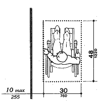
4.2.4* Clear Floor or Ground Space for Wheelchairs.
4.2.4.1 Size and Approach. The minimum clear floor or
ground space required to accommodate a single, stationary wheelchair and occupant
is 30 in by 48 in (760 mm by 1220 mm) (see Fig. 4(a)). The minimum clear floor
or ground space for wheelchairs may be positioned for forward or parallel approach
to an object (see Fig. 4(b) and (c)). Clear floor or ground space for wheelchairs
may be part of the knee space required under some objects. A
Space requirements for mobility aids other than manual wheelchairs (such as
scooters and power wheelchairs) are often greater. [future
link to Federal research]
Figure 4
Minimum Clear Floor Space for Wheelchairs
4.2.4.2 Relationship of Maneuvering Clearance to Wheelchair Spaces. One full unobstructed side of the clear floor or ground space for a wheelchair shall adjoin or overlap an accessible route or adjoin another wheelchair clear floor space. If a clear floor space is located in an alcove or otherwise confined on all or part of three sides, additional maneuvering clearances shall be provided as shown in Fig. 4(d) and (e).
4.2.4.3 Surfaces for Wheelchair Spaces. Clear floor or ground spaces for wheelchairs shall comply with 4.5.
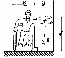
4.2.5* Forward Reach. If the clear floor space only
allows forward approach to an object, the maximum high forward reach allowed
shall be 48 in (1220 mm) (see Fig. 5(a)). The minimum
low forward reach is 15 in (380 mm). If the high forward reach is over an obstruction,
reach and clearances shall be as shown in Fig. 5(b).
UO prefers to use these dimensions as reach
limits. This is consistent with emerging standards for accessible design. A
Figure 5
Forward Reach
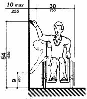
4.2.6* Side Reach. If the clear floor space allows
parallel approach by a person in a wheelchair, the maximum high side reach allowed
shall be 54 in (1370 mm) and the low side reach shall be no less than 9 in (230
mm) above the floor (Fig. 6(a) and (b)).
If the side reach is over an obstruction, the reach and clearances shall be
as shown in Fig 6(c). A
UO prefers to generally not use side reach ranges except
as shown below over obstructions.
 |
 |
 |
|
(a) Clear Floor Space, Parallel
Approach
|
(b) High and Low Side Reach
Limits
|
(c) Maximum Side Reach over
Obstruction
|
Fig. 6
Side Reach
4.3.1* General. All walks, halls, corridors,
aisles, skywalks, tunnels, and other spaces that are part of an accessible route
shall comply with 4.3. A
UO expects all areas (walks, halls, corridors,
etc.) to be accessible routes.
(1) At least one accessible route within the boundary of the site shall be provided from public transportation stops, accessible parking, and accessible passenger loading zones, and public streets or sidewalks to the accessible building entrance they serve. The accessible route shall, to the maximum extent feasible, coincide with the route for the general public.(2) At least one accessible route shall connect accessible buildings, facilities, elements, and spaces that are on the same site.
(3) At least one accessible route shall connect accessible building or facility entrances with all accessible spaces and elements and with all accessible dwelling units within the building or facility.
(4) An accessible route shall connect at least one accessible entrance of each accessible dwelling unit with those exterior and interior spaces and facilities that serve the accessible dwelling unit.
4.3.3 Width. The minimum clear width of an accessible
route shall be 36 in (915 mm) except at doors (see 4.13.5
and 4.13.6). If a person in a wheelchair must make a turn
around an obstruction, the minimum clear width of the accessible route shall
be as shown in Fig. 7(a) and (b).
UO's preferred width for accessible routes
in public areas is 60" except at doors. Please use 37" as the minimum width
to prevent problems with construction tolerances and future minor modifications
to walls.
 |
 Note: Dimensions shown apply when x<48 in (1220 mm) |
| (a) 90 degree turn | (b) Turn aournd an obstruction |
 |
 |
| (c) Changes in Level | (e) Changes in level |
4.3.4 Passing Space. If an accessible route has less than 60 in (1525 mm) clear width, then passing spaces at least 60 in by 60 in (1525 mm by 1525 mm) shall be located at reasonable intervals not to exceed 200 ft (61 m). A T-intersection of two corridors or walks is an acceptable passing place.
4.3.5 Head Room. Accessible routes shall comply
with 4.4.2.
Provide 80" clear. UO
assumes that all areas are accessible routes. Walkable surfaces with less than
80" head clearance must be reviewed and approved by UO Planning.
4.3.6 Surface Textures. The surface of an accessible route shall comply with 4.5.
4.3.7 Slope. An accessible route with a running
slope greater than 1:20 is a ramp and shall comply with 4.8.
Nowhere shall the cross slope of an accessible route exceed 1:50.
Where possible, UO prefers slopes of 1:20
or less so that curbs, landings, and handrails are not required. However, if
a route at any slope is above a steep slope, UO standard is to provide a curb
at least 2" high separating the route from the hazardous slope.
4.3.8 Changes in Levels. Changes in levels along an accessible route shall comply with 4.5.2. If an accessible route has changes in level greater than 1/2 in (13 mm), then a curb ramp, ramp, elevator, or platform lift (as permitted in 4.1.3 and 4.1.6) shall be provided that complies with 4.7, 4.8, 4.10, or 4.11, respectively. An accessible route does not include stairs, steps, or escalators. See definition of "egress, means of" in 3.5.
4.3.9 Doors. Doors along an accessible route shall comply with 4.13.
4.3.10* Egress. Accessible routes serving any accessible space or element shall also serve as a means of egress for emergencies or connect to an accessible area of rescue assistance. A
4.3.11 Areas of Rescue Assistance.
UO prefers sprinklered buildings over areas of rescue assistance.
4.3.11.1 Location and Construction. An area of rescue assistance shall be one of the following:
(1) A portion of a stairway landing within a smokeproof enclosure (complying with local requirements).(2) A portion of an exterior exit balcony located immediately adjacent to an exit stairway when the balcony complies with local requirements for exterior exit balconies. Openings to the interior of the building located within 20 feet (6 m) of the area of rescue assistance shall be protected with fire assemblies having a three- fourths hour fire protection rating.
(3) A portion of a one-hour fire-resistive corridor (complying with local requirements for fire-resistive construction and for openings) located immediately adjacent to an exit enclosure.
(4) A vestibule located immediately adjacent to an exit enclosure and constructed to the same fire-resistive standards as required for corridors and openings.
(5) A portion of a stairway landing within an exit enclosure which is vented to the exterior and is separated from the interior of the building with not less than one-hour fire-resistive doors.
OSSC: Oregon code prefers this approach.(6) When approved by the appropriate local authority, an area or a room which is separated from other portions of the building by a smoke barrier. Smoke barriers shall have a fire-resistive rating of not less than one hour and shall completely enclose the area or room. Doors in the smoke barrier shall be tight-fitting smoke- and draft-control assemblies having a fire-protection rating of not less than 20 minutes and shall be self-closing or automatic closing. The area or room shall be provided with an exit directly to an exit enclosure. Where the room or area exits into an exit enclosure which is required to be of more than one-hour fire- resistive construction, the room or area shall have the same fire- resistive construction, including the same opening protection, as required for the adjacent exit enclosure.
(7) An elevator lobby when elevator shafts and adjacent lobbies are pressurized as required for smokeproof enclosures by local regulations and when complying with requirements herein for size, communication, and signage. Such pressurization system shall be activated by smoke detectors on each floor located in a manner approved by the appropriate local authority. Pressurization equipment and its duct work within the building shall be separated from other portions of the building by a minimum two-hour fire- resistive construction.
4.3.11.3* Stairway Width. Each stairway adjacent to an area of rescue assistance shall have a minimum clear width of 48 inches between handrails. A
4.3.11.4* Two-way Communication. A method of two-way communication, with both visible and audible signals, shall be provided between each area of rescue assistance and the primary entry. The fire department or appropriate local authority may approve a location other than the primary entry. A
4.3.11.5 Identification. Each area of rescue assistance shall be identified by a sign which states "AREA OF RESCUE ASSISTANCE" and displays the international symbol of accessibility. The sign shall be illuminated when exit sign illumination is required. Signage shall also be installed at all inaccessible exits and where otherwise necessary to clearly indicate the direction to areas of rescue assistance. In each area of rescue assistance, instructions on the use of the area under emergency conditions shall be posted adjoining the two-way communication system.
4.4.1* General. Objects projecting from walls (for
example, telephones) with their leading edges between 27 in and 80 in (685 mm
and 2030 mm) above the finished floor shall protrude no more than 4 in (100
mm) into walks, halls, corridors, passageways, or aisles (see
Fig. 8(a)). Objects mounted with their leading edges at or below 27 in (685
mm) above the finished floor may protrude any amount (see
Fig. 8(a) and (b)). Free-standing objects mounted
on posts or pylons may overhang 12 in (305 mm) maximum from 27 in to 80 in (685
mm to 2030 mm) above the ground or finished floor (see
Fig. 8(c) and (d)). Protruding objects shall not
reduce the clear width of an accessible route or maneuvering space (see
Fig. 8(e)). A
?
Please pay particular attention to this
requirement. UO continues to have problems with protrusion compliance in new and renovation construction
projects.
 |
 |
| Fig. 8(a) Walking Parallel to a Wall | Fig. 8(b) Walking Perpendicular to a Wall |
 |
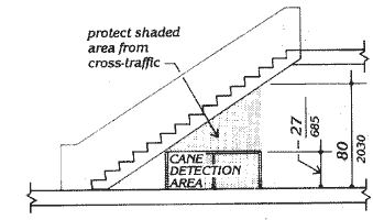 |
| Fig. 8(c) Free-Standing Overhanging Objects | Fig. 8(c-1) Overhead Hazards |
 |
|
| Fig. 8(d) Objects Mounted on Posts or Pylons |
 |
| Fig. 8(e) Protection at Wall-mounted objects |
4.4.2 Head Room. Walks, halls, corridors, passageways, aisles, or other circulation spaces shall have 80 in (2030 mm) minimum clear head room (see Fig. 8(a)). If vertical clearance of an area adjoining an accessible route is reduced to less than 80 in (nominal dimension), a barrier to warn blind or visually-impaired persons shall be provided (see Fig. 8(c-1)).
4.5 Ground and Floor Surfaces.
4.5.1* General. Ground and floor surfaces along accessible routes and in accessible rooms and spaces including floors, walks, ramps, stairs, and curb ramps, shall be stable, firm, slip-resistant, and shall comply with 4.5. A
4.5.2 Changes in Level. Changes in level up to 1/4 in (6 mm) may be vertical and without edge treatment (see Fig. 7(c) ). Changes in level between 1/4 in and 1/2 in (6 mm and 13 mm) shall be beveled with a slope no greater than 1:2 (see Fig. 7(d) ). Changes in level greater than 1/2 in (13 mm) shall be accomplished by means of a ramp that complies with 4.7 or 4.8.
4.5.3* Carpet. If carpet or carpet tile is used on a ground or floor surface, then it shall be securely attached; have a firm cushion, pad, or backing, or no cushion or pad; and have a level loop, textured loop, level cut pile, or level cut/uncut pile texture. The maximum pile thickness shall be 1/2 in (13 mm) (see Fig. 8(f)). Exposed edges of carpet shall be fastened to floor surfaces and have trim along the entire length of the exposed edge. Carpet edge trim shall comply with 4.5.2. A
 Fig.
8(f) Carpet Pile Thickness
Fig.
8(f) Carpet Pile Thickness
4.5.4 Gratings. If gratings are located in walking surfaces, then they shall have spaces no greater than 1/2 in (13 mm) wide in one direction (seeFig. 8(g)). If gratings have elongated openings, then they shall be placed so that the long dimension is perpendicular to the dominant direction of travel (see Fig. 8(h)).
 |
 |
| Fig. 8(g) Gratings | Fig. 8(h) Grating Orientation |
4.6 Parking and Passenger Loading Zones.
4.6.1 Minimum Number. Parking spaces required to be accessible by 4.1 shall comply with 4.6.2 through 4.6.5. Passenger loading zones required to be accessible by 4.1 shall comply with 4.6.5 and 4.6.6.
4.6.2 Location. Accessible parking spaces serving a particular building shall be located on the shortest accessible route of travel from adjacent parking to an accessible entrance. In parking facilities that do not serve a particular building, accessible parking shall be located on the shortest accessible route of travel to an accessible pedestrian entrance of the parking facility. In buildings with multiple accessible entrances with adjacent parking, accessible parking spaces shall be dispersed and located closest to the accessible entrances.
|
4.6.3* Parking Spaces. Accessible parking
spaces shall be at least 96 in (2440 mm) wide. Parking access aisles shall
be part of an accessible route to the building or facility entrance and
shall comply with 4.3. Two accessible parking spaces
may share a common access aisle (see Fig. 9).
Parked vehicle overhangs shall not reduce the clear width of an accessible
route. Parking spaces and access aisles shall be level with surface slopes
not exceeding 1:50 (2%) in all directions. A Fig. 9 |
|
4.6.4* Signage. Accessible parking spaces
shall be designated as reserved by a sign showing the symbol of accessibility
(see 4.30.7). Spaces complying with 4.1.2(5)(b)
shall have an additional sign "Van-Accessible" mounted below the symbol of accessibility.
Such signs shall be located so they cannot be obscured by a vehicle parked in
the space. UO accepts a height
of 48" as meeting this requirment.
OSSC: Note that State of Oregon requires signage
with specific language per their statutes.
4.6.5* Vertical Clearance. Provide minimum vertical clearance of 114 in (2895 mm) at accessible passenger loading zones and along at least one vehicle access route to such areas from site entrance(s) and exit(s). At parking spaces complying with 4.1.2(5)(b), provide minimum vertical clearance of 98 in (2490 mm) at the parking space and along at least one vehicle access route to such spaces from site entrance(s) and exit(s).
|
4.6.6 Passenger Loading Zones. Passenger loading zones shall provide an access aisle at least 60 in (1525 mm) wide and 20 ft (240 in)(6100 mm) long adjacent and parallel to the vehicle pull-up space (see Fig. 10). If there are curbs between the access aisle and the vehicle pull-up space, then a curb ramp complying with 4.7 shall be provided. Vehicle standing spaces and access aisles shall be level with surface slopes not exceeding 1:50 (2%) in all directions. Fig. 10 |
 |
4.7.1 Location. Curb ramps complying with 4.7 shall
be provided wherever an accessible route crosses a curb.
In order to provide the safest environment
possible for the blind and visually impaired, please provide an offset as shown
in Fig. 15(b) if possible.
|
4.7.2 Slope. Slopes of curb ramps shall comply
with 4.8.2. The slope shall be measured as shown
in Fig. 11. Transitions from ramps to walks,
gutters, or streets shall be flush and free of abrupt changes. Maximum
slopes of adjoining gutters, road surface immediately adjacent to the
curb ramp, or accessible route shall not exceed 1:20. |
 Fig. 11 Measurement of Curb Ramp Slopes |
4.7.3 Width. The minimum width of a curb ramp shall be 36 in (915 mm), exclusive of flared sides.
4.7.4 Surface. Surfaces of curb ramps shall comply with 4.5.
4.7.5 Sides of Curb Ramps. If a curb ramp is located where pedestrians must walk across the ramp, or where it is not protected by handrails or guardrails, it shall have flared sides; the maximum slope of the flare shall be 1:10 (see Fig. 12(a)). Curb ramps with returned curbs may be used where pedestrians would not normally walk across the ramp (see Fig. 12(b)). Returned curbs are preferred in locations with a planting strip to give a clear edge to guide crossing for blind and low-vision pedestrians.
|
Fig. 12a |
Fig. 12b |
Fig. 12 Sides of Curb Ramps
|
4.7.6 Built-up Curb Ramps. Built-up curb ramps shall be located so that they do not project into vehicular traffic lanes (see Fig. 13).
Fig. 13 |
 |
4.7.7 Detectable Warnings. A curb ramp shall have a detectable warning complying with 4.29.2.
The detectable warning shall extend the full width and depth of the curb ramp.
As a general practice, UO, expects detectable warnings at pedestrian hazard
areas such as sidewalks that meet streets, parking lots, or driveways, except in residential areas, for people who are blind or low vision to feel underfoot.
4.7.8 Obstructions. Curb ramps shall be located or protected to prevent their obstruction by parked vehicles.
4.7.9 Location at Marked Crossings. Curb ramps at
marked crossings shall be wholly contained within the markings, excluding any
flared sides. (see Fig. 15).
Offset of curb ramps from detectable edges such as buildings
or planting strips is preferred, as in Fig. 15(a) rather than Fig. 15 (b).
4.7.10 Diagonal Curb Ramps. If diagonal (or corner type) curb ramps have returned curbs or other well-defined edges, such edges shall be parallel to the direction of pedestrian flow. The bottom of diagonal curb ramps shall have 48 in (1220 mm) minimum clear space as shown in Fig. 15(c) and (d). If diagonal curb ramps are provided atmarked crossings, the 48 in (1220 mm) clear space shall be within the markings (see Fig. 15(c) and (d)). If diagonal curb ramps have flared sides, they shall also have at least a 24 in (610 mm) long segment of straight curb located on each side of the curb ramp and within the marked crossing (see Fig. 15(c)). UO generally doesn't approve diagonal curb ramps because of the crossing difficulties that they create for blind and low-vision pedestrians. This is in keeping with standards of the City of Eugene.
|
(a) |
(b) |
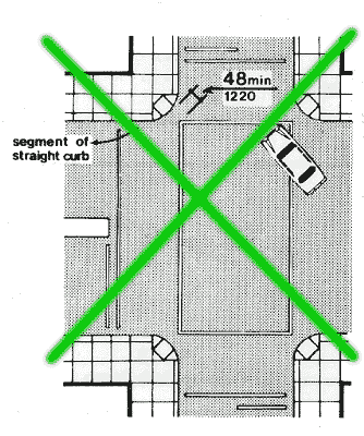 (c) |
(d) |
Fig. 15
Curb Ramps at Marked Crossings
4.7.11 Islands. Any raised islands in crossings shall be cut through level with the street or have curb ramps at both sides and a level area at least 48 in (1220 mm) long between the curb ramps in the part of the island intersected by the crossings (see Fig. 15(a) and (b)). "Level" is a slope not exceeding 2% in any direction. UO prefers all islands to provide a level 60" diameter turning circle.
4.8.1* General. Any part of an accessible route with a slope greater than 1:20 shall be considered a ramp and shall comply with 4.8. A
4.8.2* Slope and Rise. The least possible slope
shall be used for any ramp. The maximum slope of a ramp in new construction
shall be 1:12. The maximum rise for any run shall be 30 in (760 mm) (see Fig.
16). Curb ramps and ramps to be constructed on existing sites or in existing
buildings or facilities may have slopes and rises as allowed in 4.1.6(3)(a)
if space limitations prohibit the use of a 1:12 slope or less. A
Where
possible, UO prefers slopes of 1:20 or less because curbs, landings, and handrails
are not required. Where curved ramps are proposed, coordinate early in the design
process with Planning. Slope of cuved ramps will be measured at the point of
maximum slope, usually the inside edge of the curve.
| Slope |
Maximum Rise
|
Maximum Horizontal Projection
|
||
|
in
|
mm
|
ft
|
m
|
|
|
|
|
|||
| 1:12 to <1:16 |
30
|
760
|
30
|
9
|
| 1:16 to <1:20 |
30
|
760
|
40
|
12 |
Fig. 16
Components of a Single Ramp Run and Sample Ramp Dimensions
4.8.3 Clear Width. The minimum clear width of a ramp shall be 36 in (915 mm). UO interprets this meaning 36 in clear between the narrowest obstruction (often handrails), and prefers a width no less than 37" to account for construction tolerance issues.
4.8.4* Landings. Ramps shall have level landings at bottom and top of each ramp and each ramp run. Landings shall have the following features: A
(1) The landing shall be at least as wide as the ramp run leading to it.(2) The landing length shall be a minimum of 60 in (1525 mm) clear.
OSSC: Oregon code requires a 6' minimum length at bottom landings.(3) If ramps change direction at landings, the minimum landing size shall be 60 in by 60 in (1525 mm by 1525 mm).
(4) If a doorway is located at a landing, then the area in front of the doorway shall comply with 4.13.6.
4.8.5* Handrails. If a ramp run has a rise greater than 6 in (150 mm) or a horizontal projection greater than 72 in (1830 mm), then it shall have handrails on both sides. Handrails are not required on curb ramps or adjacent to seating in assembly areas. Handrails shall comply with 4.26 and shall have the following features: A
(1) Handrails shall be provided along both sides of ramp segments. The inside handrail on switchback or dogleg ramps shall always be continuous. (2) If handrails are not continuous, they shall extend at least 12 in (305 mm) beyond the top and bottom of the ramp segment and shall be parallel with the floor or ground surface (see Fig. 17).
(3) The clear space between the handrail and the wall shall be 1 - 1/2 in (38 mm).
(4) Gripping surfaces shall be continuous.
Return of the end rail to ground instead of looping back is acceptable, and sometimes preferred, as shown in green in Fig. 17.
Fig. 17
Examples of Edge Protection and Handrail Extensions
(5) Top of handrail gripping surfaces shall be mounted between 34 in and 38 in (865 mm and 965 mm) above ramp surfaces.
(6) Ends of handrails shall be either rounded or returned smoothly to floor, wall, or post.
(7) Handrails shall not rotate within their fittings.
4.8.6 Cross Slope and Surfaces. The cross slope of ramp surfaces shall be no greater than 1:50. Ramp surfaces shall comply with 4.5.
4.8.7 Edge Protection. Ramps and landings with drop-offs
shall have curbs, walls, railings, or projecting surfaces that prevent people
from slipping off the ramp. Curbs shall be a minimum of 2 in (50 mm) high (see
Fig. 17).
If a route at any slope is above a steep
slope, UO requests edge protection at least 2" high separating the route from the hazardous
slope as well as possibly guardrails or handrails. Be careful to avoid cross-slopes
exceeding 2%. ?
4.8.8 Outdoor Conditions. Outdoor ramps and their
approaches shall be designed so that water will not accumulate on walking surfaces.
UO applies this standard to all outdoor accessible routes.
4.9.1* Minimum Number. Stairs required to be accessible
by 4.1 shall comply with 4.9.
UO requires
all exterior stairs to comply, but does not require compliance at interior stairs
connecting levels served by an elevator. ?
4.9.2 Treads and Risers. On any given flight of stairs, all steps shall have uniform riser heights and uniform tread widths. Stair treads shall be no less than 11 in (280 mm) wide, measured from riser to riser (see Fig. 18(a)). Open risers are not permitted.
4.9.3 Nosings. The undersides of nosings shall not be abrupt. The radius of curvature at the leading edge of the tread shall be no greater than 1/2 in (13 mm). Risers shall be sloped or the underside of the nosing shall have an angle not less than 60 degrees from the horizontal. Nosings shall project no more than 1-1/2 in (38 mm) (see Fig. 18).
|
|
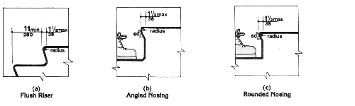 |
4.9.4 Handrails. Stairways shall have handrails at both sides of all stairs. Handrails shall comply with 4.26 and shall have the following features: A
(1) Handrails shall be continuous along both sides of stairs. The inside handrail on switchback or dogleg stairs shall always be continuous (see Fig. 19(a) and (b)).
(a) Plan
(b)
Elevation of Center Handrail
(d)
Extension at Top of Run
Fig. 19
Stair Handrails
Handrail extensions can return straight to floor, as shown in green.(2) If handrails are not continuous, they shall extend at least 12 in (305 mm) beyond the top riser and at least 12 in (305 mm) plus the width of one tread beyond the bottom riser. At the top, the extension shall be parallel with the floor or ground surface. At the bottom, the handrail shall continue to slope for a distance of the width of one tread from the bottom riser; the remainder of the extension shall be horizontal (see Fig. 19(c) and (d)). Handrail extensions shall comply with 4.4.
(3) The clear space between handrails and wall shall be 1-1/2 in (38 mm).
(4) Gripping surfaces shall be uninterrupted by newel posts, other construction elements, or obstructions.
(5) Top of handrail gripping surface shall be mounted between 34 in and 38 in (865 mm and 965 mm) above stair nosings.
(6) Ends of handrails shall be either rounded or returned smoothly to floor, wall or post.
(7) Handrails shall not rotate within their fittings.
4.9.5 Detectable Warnings at Stairs. (Reserved).
4.9.6 Outdoor Conditions. Outdoor stairs and their approaches shall be designed so that water will not accumulate on walking surfaces.
4.10.1 General. Accessible elevators shall be on an accessible route and shall comply with 4.10 and with the ASME A17.1-1990, Safety Code for Elevators and Escalators. Freight elevators shall not be considered as meeting the requirements of this section unless the only elevators provided are used as combination passenger and freight elevators for the public and employees.
4.10.2 Automatic Operation. Elevator operation shall be automatic. Each car shall be equipped with a self-leveling feature that will automatically bring the car to floor landings within a tolerance of 1/2 in (13 mm) under rated loading to zero loading conditions. This self-leveling feature shall be automatic and independent of the operating device and shall correct the overtravel or undertravel.
|
4.10.3 Hall Call Buttons. Call buttons in
elevator lobbies and halls shall be centered at 42 in (1065 mm) above
the floor. Such call buttons shall have visual signals to indicate when
each call is registered and when each call is answered. Call buttons shall
be a minimum of 3/4 in (19 mm) in the smallest dimension. The button designating
the up direction shall be on top. (See Fig. 20.) Buttons shall be raised
or flush. Objects mounted beneath hall call buttons shall not project
into the elevator lobby more than 4 in (100 mm).
4.10.4 Hall Lanterns. A visible and audible signal shall be provided at each hoistway entrance to indicate which car is answering a call. Audible signals shall sound once for the up direction and twice for the down direction or shall have verbal annunciators that say "up" or "down." Visible signals shall have the following features: (1) Hall lantern fixtures shall be mounted so that their centerline is at least 72 in (1830 mm) above the lobby floor. (See Fig. 20.) |
Fig. 20 |
4.10.5 Raised and Braille Characters on Hoistway Entrances. All elevator hoistway entrances shall have raised and Braille floor designations provided on both jambs. The centerline of the characters shall be 60 in (1525 mm) above finish floor. Such characters shall be 2 in (50 mm) high and shall comply with 4.30.4. Permanently applied plates are acceptable if they are permanently fixed to the jambs. (See Fig. 20).
4.10.6* Door Protective and Reopening Device. Elevator doors shall open and close automatically. They shall be provided with a reopening device that will stop and reopen a car door and hoistway door automatically if the door becomes obstructed by an object or person. The device shall be capable of completing these operations without requiring contact for an obstruction passing through the opening at heights of 5 in and 29 in (125 mm and 735 mm) above finish floor (see Fig. 20). Door reopening devices shall remain effective for at least 20 seconds. After such an interval, doors may close in accordance with the requirements of ASME A17.1-1990.
|
4.10.7* Door and Signal Timing for Hall Calls. The minimum acceptable time from notification that a car is answering a call until the doors of that car start to close shall be calculated from the following equation: where T total time in seconds and D distance (in feet or millimeters)
from a point in the lobby or corridor 60 in (1525 mm) directly in front
of the farthest call button controlling that car to the centerline of
its hoistway door (see Fig. 21). For cars with in-car lanterns, T begins
when the lantern is visible from the vicinity of hall call buttons and
an audible signal is sounded. The minimum acceptable notification time
shall be 5 seconds. Fig. 21 |
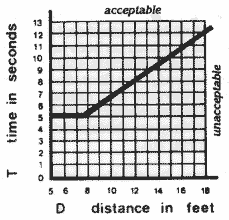 |
4.10.8 Door Delay for Car Calls. The minimum time for elevator doors to remain fully open in response to a car call shall be 3 seconds.
4.10.9 Floor Plan of Elevator Cars. The floor area of elevator cars shall provide space for wheelchair users to enter the car, maneuver within reach of controls, and exit from the car. Acceptable door opening and inside dimensions shall be as shown in Fig. 22. The clearance between the car platform sill and the edge of any hoistway landing shall be no greater than 1-1/4 in (32 mm).
|
4.10.10 Floor Surfaces. Floor surfaces shall comply with 4.5. 4.10.11 Illumination Levels. The level of illumination at the car controls, platform, and car threshold and landing sill shall be at least 5 footcandles (53.8 lux).4.10.12* Car Controls. Elevator control panels shall have the following features: (1) Buttons. All control buttons shall be at least 3/4 in (19 mm) in their smallest dimension. They shall be raised or flush. |
|
(a) Panel Detail
(b)
Car Control Height
(c)
Alternate Locations of Panel
with Center Opeing Door
(d)
Alternate Locations of Panel
with Side Opening DoorFig. 23
Car Controls(3) Height. All floor buttons shall be no higher than 54 in (1370 mm) above the finish floor for side approach and 48 in (1220 mm) for front approach. Emergency controls, including the emergency alarm and emergency stop, shall be grouped at the bottom of the panel and shall have their centerlines no less than 35 in (890 mm) above the finish floor (see Fig. 23(a) and (b)).
Front approach dimensions are preferred.(4) Location. Controls shall be located on a front wall if cars have center opening doors, and at the side wall or at the front wall next to the door if cars have side opening doors (see Fig. 23(c) and (d)).
4.10.13* Car Position Indicators. In elevator cars, a visual car position indicator shall be provided above the car control panel or over the door to show the position of the elevator in the hoistway. As the car passes or stops at a floor served by the elevators, the corresponding numerals shall illuminate, and an audible signal shall sound. Numerals shall be a minimum of 1/2 in (13 mm) high. The audible signal shall be no less than 20 decibels with a frequency no higher than 1500 Hz. An automatic verbal announcement of the floor number at which a car stops or which a car passes may be substituted for the audible signal.
4.10.14* Emergency Communications. If provided, emergency two-way communication systems between the elevator and a point outside the hoistway shall comply with ASME A17.1-1990. The highest operable part of a two-way communication system shall be a maximum of 48 in (1220 mm) from the floor of the car. It shall be identified by a raised symbol and lettering complying with 4.30 and located adjacent to the device. If the system uses a handset then the length of the cord from the panel to the handset shall be at least 29 in (735 mm). If the system is located in a closed compartment the compartment door hardware shall conform to 4.27, Controls and Operating Mechanisms. The emergency intercommunication system shall not require voice communication.
4.11 Platform Lifts (Wheelchair Lifts).
4.11.1 Location. Platform lifts (wheelchair lifts)
permitted by 4.1 shall comply with the requirements of 4.11.
Use platform lifts only with advance approval
of University Planning. Under most circumstances Planning does not approve the
installation of platform or stair-climbing lifts. For further information, refer
to UO Appendix: Lifts (forthcoming).
4.11.2* Other Requirements. If platform lifts (wheelchair lifts) are used, they shall comply with 4.2.4, 4.5, 4.27, and ASME A17.1 Safety Code for Elevators and Escalators, Section XX, 1990.
4.11.3 Entrance. If platform lifts are used then
they shall facilitate unassisted entry, operation, and exit from the lift in
compliance with 4.11.2.
Hinged gates and doors are expected to comply
with 4.13, and many gates and doors on commercial lifts do not comply.
4.12.1* General. (Reserved).
4.12.2* Window Hardware. (Reserved).
4.13.1 General. Doors required to be accessible by 4.1 shall comply with the requirements of 4.13.
4.13.2 Revolving Doors and Turnstiles. Revolving
doors or turnstiles shall not be the only means of passage at an accessible
entrance or along an accessible route. An accessible gate or door shall be provided
adjacent to the turnstile or revolving door and shall be so designed as to facilitate
the same use pattern.
UO interprets this as requiring an accessible
gate or door visible from all approaches to the turnstile or revolving door.
If the gate or door requires a staffed attendant for security purposes, the
gate or door will be staffed at all times that the facility is open.
4.13.3 Gates. Gates, including ticket gates, shall meet all applicable specifications of 4.13.
4.13.4 Double-Leaf Doorways. If doorways have two independently operated door leaves, then at least one leaf shall meet the specifications in 4.13.5 and 4.13.6. That leaf shall be an active leaf.
|
|
Fig. 24
Clear Doorway Width and Depth
EXCEPTION: Doors not requiring full user passage, such as shallow closets, may have the clear opening reduced to 20 in (510 mm) minimum.
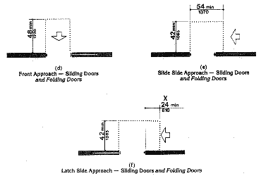

Fig 25
Maneuvering Clearances at Doors
|
4.13.7 Two Doors in Series. The minimum space between two hinged or pivoted doors in series shall be 48 in (1220 mm) plus the width of any door swinging into the space. Doors in series shall swing either in the same direction or away from the space between the doors (see Fig. 26). |
4.13.8* Thresholds at Doorways. Thresholds at doorways shall not exceed 3/4 in (19 mm) in height for exterior sliding doors or 1/2 in (13 mm) for other types of doors. Raised thresholds and floor level changes at accessible doorways shall be beveled with a slope no greater than 1:2 (see 4.5.2).
4.13.9* Door Hardware. Handles, pulls, latches,
locks, and other operating devices on accessible doors shall have a shape that
is easy to grasp with one hand and does not require tight grasping, tight pinching,
or twisting of the wrist to operate. Lever-operated mechanisms, push-type mechanisms,
and U-shaped handles are acceptable designs. When sliding doors are fully open,
operating hardware shall be exposed and usable from both sides. Hardware required
for accessible door passage shall be mounted no higher than 48 in (1220 mm)
above finished floor.
Hardware that can be operated with a closed
fist meets this standard.
4.13.10* Door Closers. If a door has a closer, then the sweep period of the closer shall be adjusted so that from an open position of 70 degrees, the door will take at least 3 seconds to move to a point 3 in (75 mm) from the latch, measured to the leading edge of the door.
4.13.11* Door Opening Force. The maximum force for pushing or pulling open a door shall be as follows:
(1) Fire doors shall have the minimum opening force allowable by the appropriate administrative authority. UO standard is no more than 7 lbs.(2) Other doors.
(a) exterior hinged doors: (Reserved). OSSC: State of Oregon and UO standard is 8.5 lb
(b) interior hinged doors: 5 lbf (22.2N)
(c) sliding or folding doors: 5 lbf (22.2N)These forces do not apply to the force required to retract latch bolts or disengage other devices that may hold the door in a closed position.
4.13.12* Automatic Doors and Power-Assisted Doors.
If an automatic door is used, then it shall comply with ANSI/BHMA A156.10-1985.
Slowly opening, low-powered, automatic doors shall comply with ANSI A156.19-1984.
Such doors shall not open to back check faster than 3 seconds and shall require
no more than 15 lbf (66.6N) to stop door movement. If a power-assisted door
is used, its door-opening force shall comply with 4.13.11
and its closing shall conform to the requirements in ANSI A156.19-1984.
Each building that is constructed or substantially altered at UO must have at
least on primary entrance equipped with a power-assisted door. See diagram
regarding placement of operator push-plate actuator. UO standard centers the
push-plate actuator centered at 42" high consistent with elevator call buttons.
4.14.1 Minimum Number. Entrances required to be accessible by 4.1 shall be part of an accessible route complying with 4.3. Such entrances shall be connected by an accessible route to public transportation stops, to accessible parking and passenger loading zones, and to public streets or sidewalks if available (see 4.3.2(1)). They shall also be connected by an accessible route to all accessible spaces or elements within the building or facility. UO expects all entrances to be accessible. Exceptions should be submitted for approval early in the design process.
4.14.2 Service Entrances. A service entrance shall not be the sole accessible entrance unless it is the only entrance to a building or facility (for example, in a factory or garage).
4.15 Drinking Fountains and Water Coolers.
4.15.1Minimum Number. Drinking fountains or water coolers required to be accessible by 4.1 shall comply with 4.15.
4.15.2*Spout Height. Spouts shall be no higher than 36 in (915 mm), measured from the floor or ground surfaces to the spout outlet (see Fig. 27(a)).
|
(a) Spout Height and Knee Clearance |
|
|
(d) Built-in Fountain or Cooler normally not allowed at UO |
Fig. 27
Drinking Fountains and Water Coolers
4.15.3 Spout Location. The spouts of drinking fountains and water coolers shall be at the front of the unit and shall direct the water flow in a trajectory that is parallel or nearly parallel to the front of the unit. The spout shall provide a flow of water at least 4 in (100 mm) high so as to allow the insertion of a cup or glass under the flow of water. On an accessible drinking fountain with a round or oval bowl, the spout must be positioned so the flow of water is within 3 in (75 mm) of the front edge of the fountain.
4.15.4 Controls. Controls shall comply with 4.27.4. Unit controls shall be front mounted or side mounted near the front edge.
(1) Wall- and post-mounted cantilevered units shall have a clear knee space between the bottom of the apron and the floor or ground at least 27 in (685 mm) high, 30 in (760 mm) wide, and 17 in to 19 in (430 mm to 485 mm) deep (see Fig. 27(a) and (b)). Such units shall also have a minimum clear floor space 30 in by 48 in (760 mm by 1220 mm) to allow a person in a wheelchair to approach the unit facing forward.
This may create a protrusion hazard, so cane detection devices or installation in a recess may be required. See Fig. 8(e) for examples of how wing walls or alcoves can be used to solve this problem.(2) Free-standing or built-in units not having a clear space under them shall have a clear floor space at least 30 in by 48 in (760 mm by 1220 mm) that allows a person in a wheelchair to make a parallel approach to the unit (see Fig. 27(c) and (d)). This clear floor space shall comply with 4.2.4.
4.16.1 General. Accessible water closets shall comply with 4.16.
4.16.2 Clear Floor Space. Clear floor space for
water closets not in stalls shall comply with Fig. 28. Clear floor space may
be arranged to allow either a left-handed or right-handed approach. ?
Use the diagram in Fig. 28 that provides a clear space
60" x 56" (or 60" x 59", depending on water closet type) to allow
for side transfer as described in A4.16.
In alteration projects, UO allows the side clearance from side wall to water
closet center line to be reduced to 16".
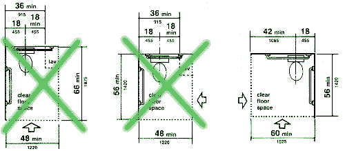
Fig. 28
Clear Floor Space at Water Closets
DO NOT USE CROSSED OUT DIAGRAMS ON UO PROJECTS
4.16.3* Height. The height of water closets shall be 17 in to 19 in
(430 mm to 485 mm), measured to the top of the toilet seat (see Fig. 29(b)).
Seats shall not be sprung to return to a lifted position.
Seat extensions are allowed.
4.16.4* Grab Bars. Grab bars for water closets not located in stalls shall comply with 4.26 and Fig. 29. The grab bar behind the water closet shall be 36 in (915 mm) minimum.
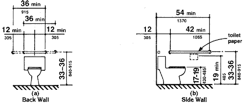
Fig. 29
Grab Bars at Water Closets
4.16.5* Flush Controls. Flush controls shall be hand operated or automatic and shall comply with 4.27.4. Controls for flush valves shall be mounted on the wide side of toilet areas no more than 44 in (1120 mm) above the floor.
4.16.6 Dispensers. Toilet paper dispensers shall be installed within reach, as shown in Fig. 29(b). Dispensers that control delivery, or that do not permit continuous paper flow, shall not be used.
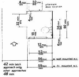
(a) |
|
|
(b) |
|
|
(d) |
Figure 30
Toilet Stalls
4.17 Toilet Stalls.
4.17.1 Location. Accessible toilet stalls shall be on an accessible route and shall meet the requirements of 4.17.
4.17.2 Water Closets. Water closets in accessible stalls shall comply with 4.16.
4.17.4 Toe Clearances. In standard stalls, the front partition and at least one side partition shall provide a toe clearance of at least 9 in (230 mm) above the floor. If the depth of the stall is greater than 60 in (1525 mm), then the toe clearance is not required.
4.17.5* Doors. Toilet stall doors, including door
hardware, shall comply with 4.13. If toilet stall approach
is from the latch side of the stall door, clearance between the door side of
the stall and any obstruction may be reduced to a minimum of 42 in (1065 mm)
(Fig. 30).
UO requires that latch hardware be accessible
per 4.13.9.
4.17.6 Grab Bars. Grab bars complying with the length and positioning shown in Fig. 30(a), (b), (c), and (d) shall be provided. Grab bars may be mounted with any desired method as long as they have a gripping surface at the locations shown and do not obstruct the required clear floor area. Grab bars shall comply with 4.26.
4.18.1 General. Accessible urinals shall comply
with 4.18.
UO may allow alteration projects to not
lower urinals where this is technically infeasible or extremely difficult due
to existing plumbing.
4.18.2 Height. Urinals shall be stall-type or wall-hung with an elongated rim at a maximum of 17 in (430 mm) above the finish floor.
4.18.3 Clear Floor Space. A clear floor space 30 in by 48 in (760 mm by 1220 mm) shall be provided in front of urinals to allow forward approach. This clear space shall adjoin or overlap an accessible route and shall comply with 4.2.4. Urinal shields that do not extend beyond the front edge of the urinal rim may be provided with 29 in (735 mm) clearance between them.
4.18.4 Flush Controls. Flush controls shall be hand operated or automatic, and shall comply with 4.27.4, and shall be mounted no more than 44 in (1120 mm) above the finish floor.
|
4.19 Lavatories and Mirrors. 4.19.1 General. The requirements of 4.19
shall apply to lavatory fixtures, vanities, and built-in lavatories.
4.19.2 Height and Clearances. Lavatories shall be mounted with the rim or counter surface no higher than 34 in (865 mm) above the finish floor. Provide a clearance of at least 29 in (735 mm) above the finish floor to the bottom of the apron. Knee and toe clearance shall comply with Fig. 31. 4.19.3 Clear Floor Space. A clear floor space 30 in by 48 in (760
mm by 1220 mm) complying with 4.2.4 shall be provided
in front of a lavatory to allow forward approach. Such clear floor space
shall adjoin or overlap an accessible route and shall extend a maximum
of 19 in (485 mm) underneath the lavatory (see Fig.
32). 4.19.4 Exposed Pipes and Surfaces. Hot water and drain pipes under lavatories shall be insulated or otherwise configured to protect against contact. There shall be no sharp or abrasive surfaces under lavatories. 4.19.5 Faucets. Faucets shall comply with 4.27.4. Lever-operated, push-type, and electronically controlled mechanisms are examples of acceptable designs. If self-closing valves are used the faucet shall remain open for at least 10 seconds. |
|
4.19.6* Mirrors. Mirrors shall be mounted with
the bottom edge of the reflecting surface no higher than 40 in (1015 mm) above
the finish floor (see Fig. 31).
In keeping with the principles of universal
design, UO requests at least one full-length mirror per restroom extending down
to 18" above the floor.
4.20.1 General. Accessible bathtubs shall comply with 4.20.
Where bathing facilities are provided, UO expects adequate
choice to be available, with provision for roll-in shower, transfer shower,
and transfer bathtub as appropriate. Please consult Campus Planning during
schematic design.
4.20.2 Floor Space. Clear floor space in front
of bathtubs shall be as shown in Fig. 33.
Additional space beyond the control wall is preferred. ?
|
|
|
|
4.20.3 Seat. An in-tub seat or a seat at the head end of the tub shall
be provided as shown in Fig. 33 and 34.
The structural strength of seats and their attachments shall comply with 4.26.3.
Seats shall be mounted securely and shall not slip during use.
If a seat at the head of the tub is provided, slope it
slightly to drain into the tub.
4.20.4 Grab Bars. Grab bars complying with 4.26 shall be provided as shown in Fig. 33 and 34.
4.20.5 Controls. Faucets and other controls complying
with 4.27.4 shall be located as shown in Fig.
34.
Location near the outside edge of the control
wall is preferred.
4.20.6 Shower Unit. A shower spray unit with a
hose at least 60 in (1525 mm) long that can be used both as a fixed shower head
and as a hand-held shower shall be provided.
Provide hardware for mounting the shower spray
at an accessible height as well as at ambulatory height.
4.20.7 Bathtub Enclosures. If provided, enclosures for bathtubs shall not obstruct controls or transfer from wheelchairs onto bathtub seats or into tubs. Enclosures on bathtubs shall not have tracks mounted on their rims.
4.21.1* General. Accessible shower stalls shall comply with 4.21.
Where bathing facilities are provided,
UO expects adequate choice to be available, with provision for roll-in shower,
transfer shower, and transfer bathtub as appropriate. Please consult Campus
Planning during schematic design.
4.21.2 Size and Clearances. Except as specified in 9.1.2, shower stall size and clear floor space shall comply with Fig. 35(a) or (b). The shower stall in Fig. 35(a) shall be 36 in by 36 in (915 mm by 915 mm). Shower stalls required by 9.1.2 shall comply with Fig. 57(a) or (b). The shower stall in Fig. 35(b) will fit into the space required for a bathtub. Additional space outside the control wall is preferred. See [link to come].
|
|
Fig. 34
Shower Size and Clearances
|
4.21.3 Seat. A seat shall be provided in shower stalls 36 in by 36 in (915 mm by 915 mm) and shall be as shown in Fig. 36. The seat shall be mounted 17 in to 19 in (430 mm to 485 mm) from the bathroom floor and shall extend the full depth of the stall. In a 36 in by 36 in (915 mm by 915 mm) shower stall, the seat shall be on the wall opposite the controls. Where a fixed seat is provided in a 30 in by 60 in minimum (760 mm by 1525 mm) shower stall, it shall be a folding type and shall be mounted on the wall adjacent to the controls as shown in Fig. 57. The structural strength of seats and their attachments shall comply with 4.26.3. 4.21.4 Grab Bars. Grab bars complying with 4.26 shall be provided as shown in Fig. 37. 4.21.5 Controls. Faucets and other controls
complying with 4.27.4 shall be located as shown
in Fig. 37. In shower stalls 36 in by 36 in (915
mm by 915 mm), all controls, faucets, and the shower unit shall be mounted
on the side wall opposite the seat.
|
4.21.6 Shower Unit. A shower spray unit with a hose at least 60 in (1525 mm) long that can be used both as a fixed shower head and as a hand-held shower shall be provided.
4.21.7 Curbs. If provided, curbs in shower stalls 36 in by 36 in (915 mm by 915 mm) shall be no higher than 1/2 in (13 mm). Shower stalls that are 30 in by 60 in (760 mm by 1525 mm) minimum shall not have curbs.
4.21.8 Shower Enclosures. If provided,
enclosures for shower stalls shall not obstruct controls or obstruct transfer
from wheelchairs onto shower seats.
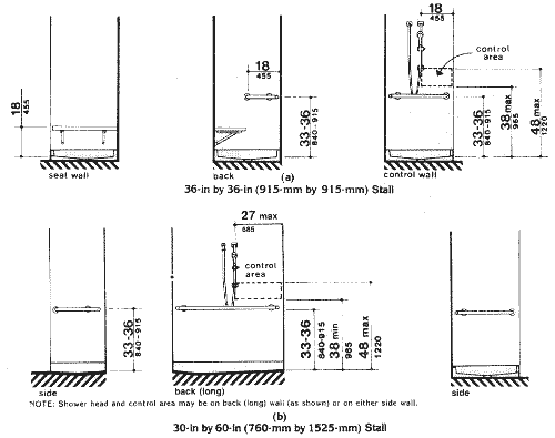
Fig. 37 Grab Bars at Shower Stalls
4.22.1 Minimum Number. Toilet facilities required to be accessible by 4.1 shall comply with 4.22. Accessible toilet rooms shall be on an accessible route.
4.22.2 Doors. All doors to accessible toilet rooms
shall comply with 4.13. Doors shall not swing into the clear
floor space required for any fixture.
4.22.3* Clear Floor Space. The accessible fixtures
and controls required in 4.22.4, 4.22.5,
4.22.6, and 4.22.7 shall be on an
accessible route. An unobstructed turning space complying with 4.2.3
shall be provided within an accessible toilet room. The clear floor space at
fixtures and controls, the accessible route, and the turning space may overlap.
In multi-user toilet rooms, none of these
clear floor spaces can overlap with the door swing. In single-user toilet rooms,
UO allows the door swing and turning circle to overlap if it is clear that a
person in a wheelchair can enter, close the door, lock the door, use the facilities,
and exit without assistance. This exception is available also in multi-user
remodel situations where it is technically infeasible to fully separate door
swing from clear spaces, as determined by Campus Planning.
4.22.4 Water Closets. If toilet stalls are provided,
then at least one shall be a standard toilet stall complying with 4.17;
where 6 or more stalls are provided, in addition to the stall complying with
4.17.3, at least one stall 36 in (915 mm)
wide with an outward swinging, self-closing door and parallel grab bars complying
with Fig. 30(d) and 4.26
shall be provided. Water closets in such stalls shall comply with 4.16.
If water closets are not in stalls, then at least one shall comply with 4.16.
Note section in bold. UO also expects new
facilities to provide one such stall for each sex in at least one restroom pair
in each major new building.
4.22.5 Urinals. If urinals are provided, then at least one shall comply with 4.18.
4.22.6 Lavatories and Mirrors. If lavatories and mirrors are provided, then at least one of each shall comply with 4.19. In addition to the requirements of this section, UO requires each multi-user toilet room to also provide a mirror that comes to within 18" of the floor. Also note that our mobility-impaired population has expressed a dislike of lavatories designed specifically for them.
4.22.7 Controls and Dispensers. If controls, dispensers, receptacles, or other equipment are provided, then at least one of each shall be on an accessible route and shall comply with 4.27.
4.23 Bathrooms, Bathing Facilities, and Shower Rooms.
4.23.1 Minimum Number. Bathrooms, bathing facilities, or shower rooms required to be accessible by 4.1 shall comply with 4.23 and shall be on an accessible route.
4.23.2 Doors. Doors to accessible bathrooms shall comply with 4.13. Doors shall not swing into the floor space required for any fixture.
4.23.3* Clear Floor Space. The accessible fixtures and controls required in 4.23.4, 4.23.5, 4.23.6, 4.23.7, 4.23.8, and 4.23.9 shall be on an accessible route. An unobstructed turning space complying with 4.2.3 shall be provided within an accessible bathroom. The clear floor spaces at fixtures and controls, the accessible route, and the turning space may overlap.
4.23.4 Water Closets. If toilet stalls are provided, then at least one shall be a standard toilet stall complying with 4.17; where 6 or more stalls are provided, in addition to the stall complying with 4.17.3, at least one stall 36 in (915 mm) wide with an outward swinging, self-closing door and parallel grab bars complying with Fig. 30(d) and 4.26 shall be provided. Water closets in such stalls shall comply with 4.16. If water closets are not in stalls, then at least one shall comply with 4.16.
4.23.5 Urinals. If urinals are provided, then at least one shall comply with 4.18.
4.23.6 Lavatories and Mirrors. If lavatories and mirrors are provided, then at least one of each shall comply with 4.19. In addition to the requirements of this section, UO requires each multi-user toilet room to also provide a mirror that comes to within 18" of the floor. Also note that our mobility-impaired population has expressed a dislike of lavatories designed specifically for them.
4.23.7 Controls and Dispensers. If controls, dispensers, receptacles, or other equipment are provided, then at least one of each shall be on an accessible route and shall comply with 4.27.
4.23.8 Bathing and Shower Facilities. If tubs or
showers are provided, then at least one accessible tub that complies with 4.20
or at least one accessible shower that complies with 4.21
shall be provided.
Where bathing facilities are provided, UO expects adequate
choice to be available, with provision for roll-in shower, transfer shower,
and transfer bathtub as appropriate. Please consult Campus Planning during
schematic design.
4.23.9* Medicine Cabinets. If medicine cabinets are provided, at least one shall be located with a usable shelf no higher than 44 in (1120 mm) above the floor space. The floor space shall comply with 4.2.4.
4.24.1 General. Sinks required to be accessible by 4.1 shall comply
with 4.24.
Although 4.1 is not clear on where accessible
sinks are required, UO requires that sinks in public use, student use, and employee
use comply with this section unless Campus Planning allows an exception.
Exceptions are used in employee-use situations such as commercial kitchens and
laboratories where these provisions may conflict with standard equipment, industry
standards, and functional requirements. In such areas we may require that provisions
for future adaptability be included, depending on the performance requirments
of the staff working in the space.
4.24.2 Height. Sinks shall be mounted with the counter or rim no higher than 34 in (865 mm) above the finish floor.
4.24.3 Knee Clearance. Knee clearance that is at least 27 in (685 mm) high, 30 in (760 mm) wide, and 19 in (485 mm) deep shall be provided underneath sinks.
4.24.4 Depth. Each sink shall be a maximum of 6-1/2 in (165 mm) deep.
4.24.5 Clear Floor Space. A clear floor space at least 30 in by 48 in (760 mm by 1220 mm) complying with 4.2.4 shall be provided in front of a sink to allow forward approach. The clear floor space shall be on an accessible route and shall extend a maximum of 19 in (485 mm) underneath the sink (see Fig. 32).
4.24.6 Exposed Pipes and Surfaces. Hot water and drain pipes exposed under sinks shall be insulated or otherwise configured so as to protect against contact. There shall be no sharp or abrasive surfaces under sinks.
4.24.7 Faucets. Faucets shall comply with 4.27.4. Lever-operated, push-type, touch-type, or electronically controlled mechanisms are acceptable designs.
4.25.1 General. Fixed storage facilities such as cabinets, shelves, closets, and drawers required to be accessible by 4.1 shall comply with 4.25.
4.25.2 Clear Floor Space. A clear floor space at least 30 in by 48 in (760 mm by 1220 mm) complying with 4.2.4 that allows either a forward or parallel approach by a person using a wheelchair shall be provided at accessible storage facilities.
4.25.3 Height. Accessible storage spaces shall be within at least one of the reach ranges specified in 4.2.5 and 4.2.6 (see Fig. 5 and Fig 6). Clothes rods or shelves shall be a maximum of 54 in (1370 mm) above the finish floor for a side approach. Where the distance from the wheelchair to the clothes rod or shelf exceeds 10 in (255 mm) (as in closets without accessible doors) the height and depth to the rod or shelf shall comply with Fig. 38(a) and Fig. 38(b).
Fig. 38 Storage Shelves and Closets
4.25.4 Hardware. Hardware for accessible storage facilities shall comply with 4.27.4. Touch latches and U-shaped pulls are acceptable.
4.26 Handrails, Grab Bars, and Tub and Shower Seats.
4.26.1* General. All handrails, grab bars, and tub and shower seats required to be accessible by 4.1, 4.8, 4.9, 4.16, 4.17, 4.20 or 4.21 shall comply with 4.26.
4.26.2* Size and Spacing of Grab Bars and Handrails.
The diameter or width of the gripping surfaces of a handrail or grab bar shall
be 1-1/4 in to 1-1/2 in (32 mm to 38 mm), or the shape shall provide an equivalent
gripping surface. If handrails or grab bars are mounted adjacent to a wall,
the space between the wall and the grab bar shall be 1-1/2 in (38 mm) (see
Fig. 39(a), (b), (c),
and (e)). Handrails may be located in a recess if
the recess is a maximum of 3 in (75 mm) deep and extends at least 18 in (455
mm) above the top of the rail (see Fig. 39(d)).
Round handrails may not be architecturally appropriate
to all projects, and alternative handrail sectionsare allowed by the UO and
by the City of Eugene. See Planning for equivalent handrail sections that are
approved.
|
|
Fig. 39
Size and Spacing of Handrails and Grab Bars
4.26.3 Structural Strength. The structural strength of grab bars, tub and shower seats, fasteners, and mounting devices shall meet the following specification:
(1) Bending stress in a grab bar or seat induced by the maximum bending moment from the application of 250 lbf (1112N) shall be less than the allowable stress for the material of the grab bar or seat.(2) Shear stress induced in a grab bar or seat by the application of 250 lbf (1112N) shall be less than the allowable shear stress for the material of the grab bar or seat. If the connection between the grab bar or seat and its mounting bracket or other support is considered to be fully restrained, then direct and torsional shear stresses shall be totaled for the combined shear stress, which shall not exceed the allowable shear stress.
(3) Shear force induced in a fastener or mounting device from the application of 250 lbf (1112N) shall be less than the allowable lateral load of either the fastener or mounting device or the supporting structure, whichever is the smaller allowable load.
(4) Tensile force induced in a fastener by a direct tension force of 250 lbf (1112N) plus the maximum moment from the application of 250 lbf (1112N) shall be less than the allowable withdrawal load between the fastener and the supporting structure.
(5) Grab bars shall not rotate within their fittings.
4.26.4 Eliminating Hazards. A handrail or grab bar and any wall or other surface adjacent to it shall be free of any sharp or abrasive elements. Edges shall have a minimum radius of 1/8 in (3.2 mm).
4.27 Controls and Operating Mechanisms.
4.27.1 General. Controls and operating mechanisms required to be accessible
by 4.1 shall comply with 4.27.
UO applies this standard broadly. Any control
normally accessible to room users needs to be accessible. This may include thermostats
and circuit breakers.
4.27.2 Clear Floor Space. Clear floor space complying with 4.2.4 that allows a forward or a parallel approach by a person using a wheelchair shall be provided at controls, dispensers, receptacles, and other operable equipment.
4.27.4 Operation. Controls and operating mechanisms
shall be operable with one hand and shall not require tight grasping, pinching,
or twisting of the wrist. The force required to activate controls shall be no
greater than 5 lbf (22.2 N).
Hardware that can be
operated with a closed fist meets this standard.
4.28.1 General. Alarm systems required to be accessible by 4.1
shall comply with 4.28. At a minimum, visual signal appliances shall be provided
in buildings and facilities in each of the following areas: restrooms and any
other general usage areas (e.g., meeting rooms), hallways, lobbies, and any
other area for common use.
UO requires designers to anticipate future
demand for additional alarms to serve the needs of individual offices, work
rooms, or sleeping rooms. In these areas, strobes, horns, or vibratory devices
may be appropriate.
4.28.2* Audible Alarms. If provided, audible emergency alarms shall produce a sound that exceeds the prevailing equivalent sound level in the room or space by at least 15 dbA or exceeds any maximum sound level with a duration of 60 seconds by 5 dbA, whichever is louder. Sound levels for alarm signals shall not exceed 120 dbA.
4.28.3* Visual Alarms. Visual alarm signal appliances
shall be integrated into the building or facility alarm system. If single station
audible alarms are provided then single station visual alarm signals shall be
provided. Visual alarm signals shall have the following minimum photometric
and location features:
Also check the provisions of NFPA. In particular,
if more than two strobes are within a field of view, provisions shall be made
so that they operate synchronously.
4.28.4* Auxiliary Alarms. Units and sleeping accommodations shall have a visual alarm connected to the building emergency alarm system or shall have a standard 110-volt electrical receptacle into which such an alarm can be connected and a means by which a signal from the building emergency alarm system can trigger such an auxiliary alarm. When visual alarms are in place the signal shall be visible in all areas of the unit or room. Instructions for use of the auxiliary alarm or receptacle shall be provided.
4.29.1 General. Detectable warnings required by 4.1 and 4.7 shall comply with 4.29.
4.29.2* Detectable Warnings on Walking Surfaces. Detectable warnings shall consist of raised truncated domes with a diameter of nominal 0.9 in (23 mm), a height of nominal 0.2 in (5 mm) and a center-to-center spacing of nominal 2.35 in (60 mm) and shall contrast visually with adjoining surfaces, either light-on-dark, or dark-on-light.
The material used to provide contrast shall be an integral part of the walking surface. Detectable warnings used on interior surfaces shall differ from adjoining walking surfaces in resiliency or sound-on-cane contact.
4.29.3 Detectable Warnings on Doors To Hazardous Areas. (Reserved).
4.29.4 Detectable Warnings at Stairs. (Reserved).
4.29.5 Detectable Warnings at Hazardous Vehicular Areas. [Provision suspended until July 26, 1998] If a walk crosses or adjoins a vehicular way, and the walking surfaces are not separated by curbs, railings, or other elements between the pedestrian areas and vehicular areas, the boundary between the areas shall be defined by a continuous detectable warning which is 36 in (915 mm) wide, complying with 4.29.2.
4.29.6 Detectable Warnings at Reflecting Pools. [Provision suspended until July 26, 1998] The edges of reflecting pools shall be protected by railings, walls, curbs, or detectable warnings complying with 4.29.2.
4.29.7 Standardization. (Reserved).
4.30 Signage.
UO Facilities Services has a standard for
accessible signage. Signs meeting this standard are available from their sign
shop.
4.30.1* General. Signage required to be accessible by 4.1 shall comply with the applicable provisions of 4.30.
4.30.2* Character Proportion. Letters and numbers
on signs shall have a width-to-height ratio between 3:5 and 1:1 and a stroke-width-to-height
ratio between 1:5 and 1:10.
UO applies these provisions to raised letter room identification
as well as other signage.
4.30.3 Character Height. Characters and numbers on signs shall be sized according to the viewing distance from which they are to be read. The minimum height is measured using an upper case X. Lower case characters are permitted.
|
Height Above |
Minimum
Character Height |
| ________________________________________________________ | |
|
Suspended or Projected Overhead in compliance with 4.4.2 |
3 in (75 mm) minimum
|
4.30.4 Raised and Brailled Characters and Pictorial Symbol Signs (Pictograms). Letters and numerals shall be raised 1/32 in (0.79 mm) minimum, upper case, sans serif or simple serif type and shall be accompanied with Grade 2 Braille. Raised characters shall be at least 5/8 in (16 mm) high, but no higher than 2 in (50 mm). Pictograms shall be accompanied by the equivalent verbal description placed directly below the pictogram. The border dimension of the pictogram shall be 6 in (152 mm) minimum in height.
4.30.5* Finish and Contrast. The characters and background of signs shall be eggshell, matte, or other non-glare finish. Characters and symbols shall contrast with their background -- either light characters on a dark background or dark characters on a light background.
4.30.6 Mounting Location and Height. Where permanent identification is provided for rooms and spaces, signs shall be installed on the wall adjacent to the latch side of the door. Where there is no wall space to the latch side of the door, including at double leaf doors, signs shall be placed on the nearest adjacent wall. Mounting height shall be 60 in (1525 mm) above the finish floor to the centerline of the sign. Mounting location for such signage shall be so that a person may approach within 3 in (76 mm) of signage without encountering protruding objects or standing within the swing of a door.
4.30.7* Symbols of Accessibility.
(1) Facilities and elements required to be identified as accessible by 4.1 shall use the international symbol of accessibility. The symbol shall be displayed as shown in Fig. 43(a) and (b).
2) Volume Control Telephones. Telephones required to have a volume control by 4.1.3(17)(b) shall be identified by a sign containing a depiction of a telephone handset with radiating sound waves.
(3) Text Telephones. Text telephones required by 4.1.3(17)(c) shall be identified by the international TDD symbol (Fig 43(c)). In addition, if a facility has a public text telephone, directional signage indicating the location of the nearest text telephone shall be placed adjacent to all banks of telephones which do not contain a text telephone. Such directional signage shall include the international TDD symbol. If a facility has no banks of telephones, the directional signage shall be provided at the entrance (e.g., in a building directory).
4) Assistive Listening Systems. In assembly areas where permanently installed assistive listening systems are required by 4.1.3(19)(b) the availability of such systems shall be identified with signage that includes the international symbol of access for hearing loss (Fig 43(d)).
4.30.8* Illumination Levels. (Reserved).
Fig. 43
International Symbols
(a)
Proportions
International Symbol of Accessibility
(b)
Display Conditions
International Symbol of Accessibility
(c)
International TDD Symbol
(d)
International Symbol of Access for
Hearing Loss
4.31.1 General. Public telephones required to be accessible by 4.1 shall comply with 4.31.
4.31.2 Clear Floor or Ground Space. A clear floor or ground space at least 30 in by 48 in (760 mm by 1220 mm) that allows either a forward or parallel approach by a person using a wheelchair shall be provided at telephones (see Fig. 44). The clear floor or ground space shall comply with 4.2.4. Bases, enclosures, and fixed seats shall not impede approaches to telephones by people who use wheelchairs.
4.31.3* Mounting Height. The highest operable part of the telephone shall be within the reach ranges specified in 4.2.5 or 4.2.6.
4.31.4 Protruding Objects. Telephones shall comply with 4.4.
4.31.5 Hearing Aid Compatible and Volume Control Telephones Required by 4.1.
(1) Telephones shall be hearing aid compatible.(2) Volume controls, capable of a minimum of 12 dbA and a maximum of 18 dbA above normal, shall be provided in accordance with 4.1.3. If an automatic reset is provided then 18 dbA may be exceeded.
4.31.6 Controls. Telephones shall have pushbutton controls where service for such equipment is available.
4.31.7 Telephone Books. Telephone books, if provided, shall be located in a position that complies with the reach ranges specified in 4.2.5 and 4.2.6.
4.31.8 Cord Length. The cord from the telephone to the handset shall be at least 29 in (735 mm) long.
4.31.9* Text Telephones Required by 4.1.
(1) Text telephones used with a pay telephone shall be permanently affixed within, or adjacent to, the telephone enclosure. If an acoustic coupler is used, the telephone cord shall be sufficiently long to allow connection of the text telephone and the telephone receiver.(2) Pay telephones designed to accommodate a portable text telephone shall be equipped with a shelf and an electrical outlet within or adjacent to the telephone enclosure. The telephone handset shall be capable of being placed flush on the surface of the shelf. The shelf shall be capable of accommodating a text telephone and shall have 6 in (152 mm) minimum vertical clearance in the area where the text telephone is to be placed.
(3) Equivalent facilitation may be provided. For example, a portable text telephone may be made available in a hotel at the registration desk if it is available on a 24-hour basis for use with nearby public pay telephones. In this instance, at least one pay telephone shall comply with paragraph 2 of this section. In addition, if an acoustic coupler is used, the telephone handset cord shall be sufficiently long so as to allow connection of the text telephone and the telephone receiver. Directional signage shall be provided and shall comply with 4.30.7.
4.32 Fixed or Built-in Seating and Tables.
UO uses these dimensions for seating at desks in classrooms.
In addition, at least one of the accessible stations in each classroom must
have a vertically-adjustable table user-adaptable to different needs.
4.32.1 Minimum Number. Fixed or built-in seating or tables required to be accessible by 4.1 shall comply with 4.32.
4.32.2 Seating. If seating spaces for people in
wheelchairs are provided at fixed tables or counters, clear floor space complying
with 4.2.4 shall be provided. Such clear floor space shall
not overlap knee space by more than 19 in (485 mm) (see
Fig. 45).
Contact Campus Planning for seating until UO standards are incorporated
into this document.
4.32.3 Knee Clearances. If seating for people in wheelchairs is provided at tables or counters, knee spaces at least 27 in (685 mm) high, 30 in (760 mm) wide, and 19 in (485 mm) deep shall be provided (see Fig. 45).
4.32.4* Height of Tables or Counters. The tops of accessible tables and counters shall be from 28 in to 34 in (710 mm to 865 mm) above the finish floor or ground.
4.33 Assembly Areas. ?
4.33.1 Minimum Number. Assembly and associated areas required to be accessible by 4.1 shall comply with 4.33.
4.33.2* Size of Wheelchair Locations. Each wheelchair
location shall provide minimum clear ground or floor spaces as shown in Fig.
46.
Contact Campus Planning for seating in assembly areas until UO standards
are incorporated into this document.
4.33.4 Surfaces. The ground or floor at wheelchair locations shall be level and shall comply with 4.5.
4.33.5 Access to Performing Areas. An accessible route shall connect wheelchair seating locations with performing areas, including stages, arena floors, dressing rooms, locker rooms, and other spaces used by performers.
4.33.6* Placement of Listening Systems. If the listening system provided serves individual fixed seats, then such seats shall be located within a 50 ft (15 m) viewing distance of the stage or playing area and shall have a complete view of the stage or playing area.
4.33.7* Types of Listening Systems. Assistive listening systems (ALS) are intended to augment standard public address and audio systems by providing signals which can be received directly by persons with special receivers or their own hearing aids and which eliminate or filter background noise. The type of assistive listening system appropriate for a particular application depends on the characteristics of the setting, the nature of the program, and the intended audience. Magnetic induction loops, infra-red and radio frequency systems are types of listening systems which are appropriate for various applications.
4.34 Automated Teller Machines.
4.34.1 General. Each machine required to be accessible by 4.1.3 shall be on an accessible route and shall comply with 4.34.
4.34.2 Clear Floor Space. The automated teller machine shall be located so that clear floor space complying with 4.2.4 is provided to allow a person using a wheelchair to make a forward approach, a parallel approach, or both, to the machine.
(1) Forward Approach Only. If only a forward approach is possible, operable parts of all controls shall be placed within the forward reach range specified in 4.2.5.(2) Parallel Approach Only. If only a parallel approach is possible, operable parts of controls shall be placed as follows:
(a) Reach Depth Not More Than 10 In (255 Mm). Where the reach depth to the operable parts of all controls as measured from the vertical plane perpendicular to the edge of the unobstructed clear floor space at the farthest protrusion of the automated teller machine or surround is not more than 10 in (255 mm), the maximum height above the finished floor or grade shall be 54 in (1370 mm).(b) Reach Depth More Than 10 In (255 Mm). Where the reach depth to the operable parts of any control as measured from the vertical plane perpendicular to the edge of the unobstructed clear floor space at the farthest protrusion of the automated teller machine or surround is more than 10 in (255 mm), the maximum height above the finished floor or grade shall be as follows:
____________________________________________________________ In Mm In Mm 10
255 54 1370 11 280 53-1/2 1360 12 305 53 1345 13 330 52-1/2 1335 14 355 51-1/2 1310 15 380 51 1295 16 405 50-1/2 1285 17 430 50 1270 18 455 49-1/2 1255 19 485 49 1245 20 510 48-1/2 1230 21 535 47-1/2 1205 22 560 47 1195 23 585 46-1/2 1180 24 610 46 1170 (3) Forward and Parallel Approach. If both a forward and parallel approach are possible, operable parts of controls shall be placed within at least one of the reach ranges in paragraphs (1) or (2) of this section.
- (4) Bins. Where bins are provided for envelopes, waste paper, or other purposes, at least one of each type provided shall comply with the applicable reach ranges in paragraph (1), (2), or (3) of this section.
- EXCEPTION: Where a function can be performed in a substantially equivalent manner by using an alternate control, only one of the controls needed to perform that function is required to comply with this section. If the controls are identified by tactile markings, such markings shall be provided on both controls.
4.34.4 Controls. Controls for user activation shall comply with 4.27.4.
4.34.5 Equipment for Persons with Vision Impairments. Instructions and all information for use shall be made accessible to and independently usable by persons with vision impairments.
4.35 Dressing and Fitting Rooms.
4.35.1 General. Dressing and fitting rooms required to be accessible
by 4.1 shall comply with 4.35 and shall be on an accessible
route.
Independent dressing rooms must be provided as an alternative to locker rooms
to provide for attendants of the opposite sex. These should allow for independent
access without having to pass through a gender-restricted area.
4.35.2 Clear Floor Space. A clear floor space allowing a person using a wheelchair to make a 180-degree turn shall be provided in every accessible dressing room entered through a swinging or sliding door. No door shall swing into any part of the turning space. Turning space shall not be required in a private dressing room entered through a curtained opening at least 32 in (815 mm) wide if clear floor space complying with section 4.2 renders the dressing room usable by a person using a wheelchair.
4.35.3 Doors. All doors to accessible dressing rooms shall be in compliance with section 4.13.
4.35.4 Bench. Every accessible dressing room shall have a 24 in by 48 in (610 mm by 1220 mm) bench fixed to the wall along the longer dimension. The bench shall be mounted 17 in to 19 in (430 mm to 485 mm) above the finish floor. Clear floor space shall be provided alongside the bench to allow a person using a wheelchair to make a parallel transfer onto the bench. The structural strength of the bench and attachments shall comply with 4.26.3. Where installed in conjunction with showers, swimming pools, or other wet locations, water shall not accumulate upon the surface of the bench and the bench shall have a slip-resistant surface.
4.35.5 Mirror. Where mirrors are provided in dressing rooms of the same use, then in an accessible dressing room, a full-length mirror, measuring at least 18 in wide by 54 in high (460 mm by 1370 mm), shall be mounted in a position affording a view to a person on the bench as well as to a person in a standing position.
Sections 11 and 12 have not been incorporated in the Department of Justice accessibility standards and are, therefore, not enforceable. For UO residential (non-dormitory) housing, use the Uniform Federal Accessibility Standards (UFAS). UO adds to this some of the requirements of ADAAG section 9, in particular the requirements for accessible sleeping rooms.

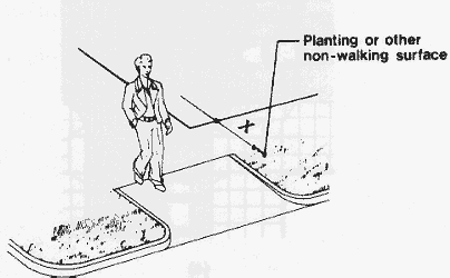
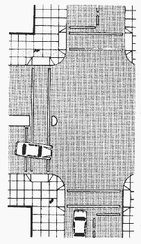
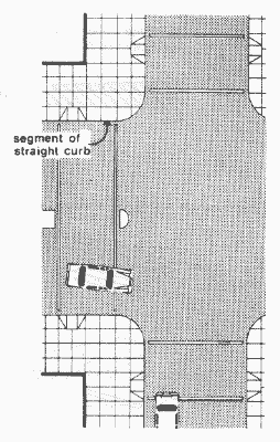
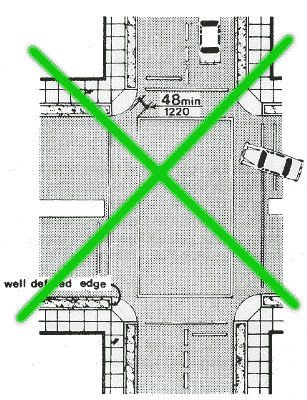

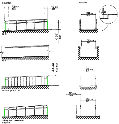
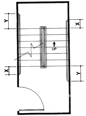
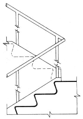
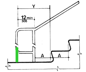


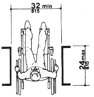

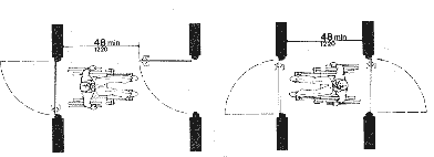
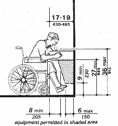
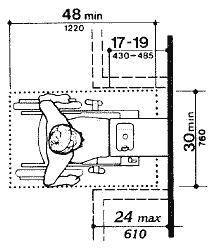
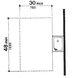
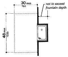
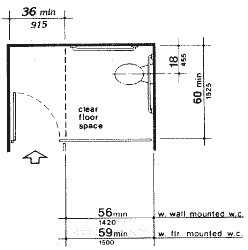
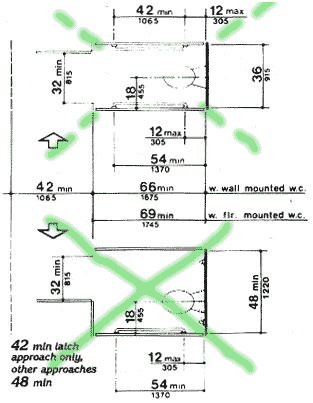
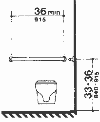
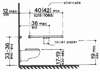
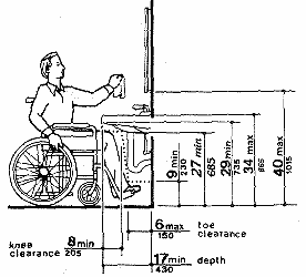
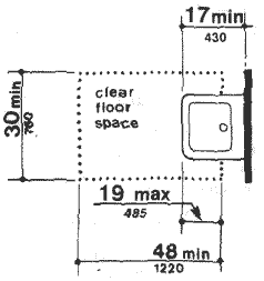
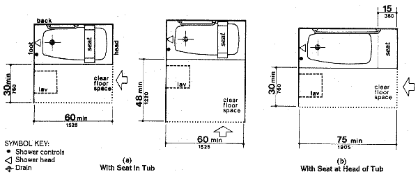
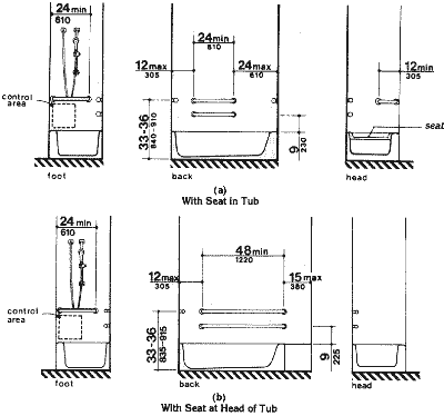
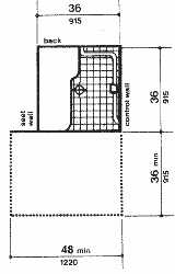
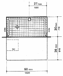


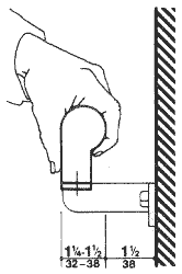
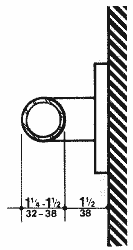


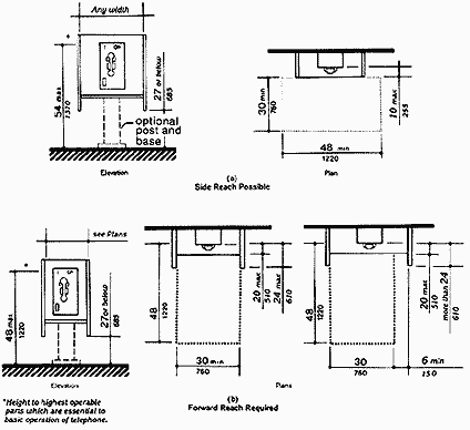
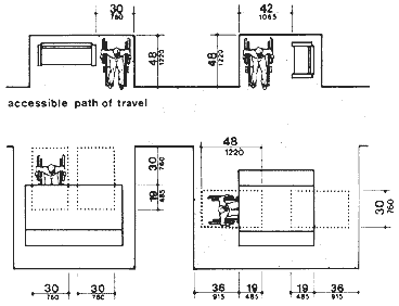
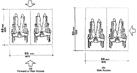
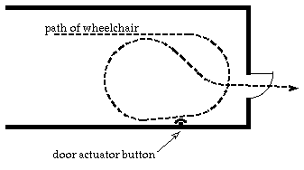