Interactive
Lecture Demonstrations
Prediction
Sheet—Introduction to DC Circuits
Directions: Click here to download the Prediction Sheet where
you will enter your predictions and answers. Write your name at the top
to record your presence and participation in these demonstrations. For
each demonstration below, write your prediction on this sheet before making any
observations. You may be asked to send this sheet to your instructor.
|
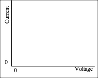
Demonstration 1: A resistor (a device that obeys
Ohm’s law) is connected to a variable source of voltage. Sketch on the right
your prediction of a graph of the current that flows through the resistor as
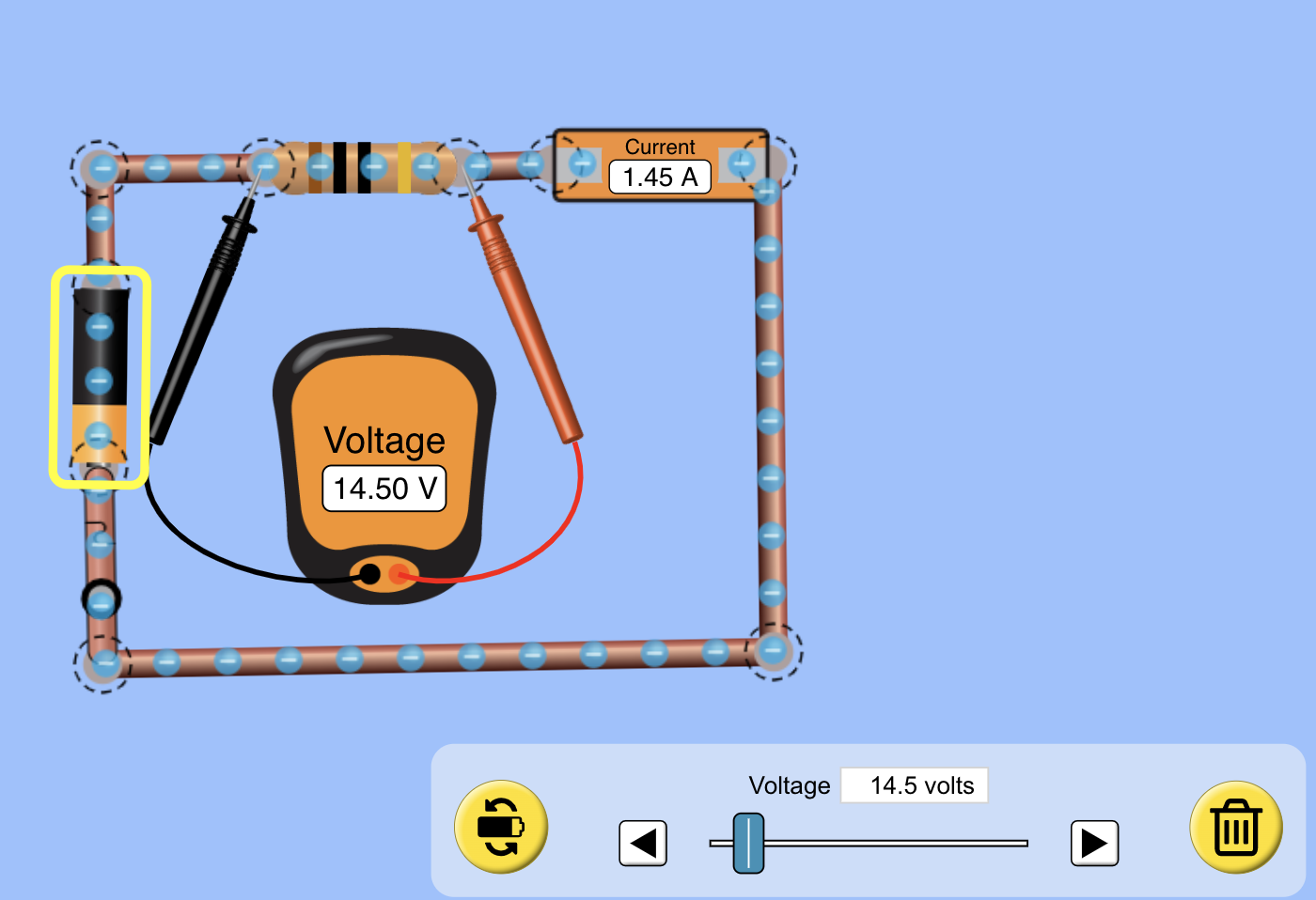
the voltage across the resistor is increased starting from zero. After you have made your prediction, open the simulation: https://phet.colorado.edu/sims/html/circuit-construction-kit-dc/latest/circuit-construction-kit-dc_en.html Click on
Lab and construct the circuit. You can look at a picture of the correct
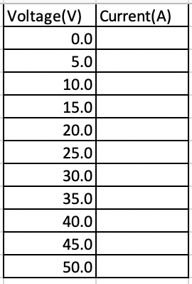
circuit here. Adjust the battery voltage in equal 5 volt steps by clicking once on the battery and adjusting
the slide switch. Record the values in the table and sketch the graph with a
dashed line. See how the current through the bulb varies and compare it to
your prediction. Explain. See how the current through the resistor varies and
compare it to your prediction. Explain. How
would you calculate the resistance of the resistor by reading values from the
graph? |
|
|
Demonstration 2: The resistance of most
conductors increases as the temperature increases. As more current flows through
the filament of a light bulb, the temperature of the filament gets higher. A
light bulb is connected to a variable source of voltage. Sketch on the right
your prediction of a graph of the current that flows through the light bulb
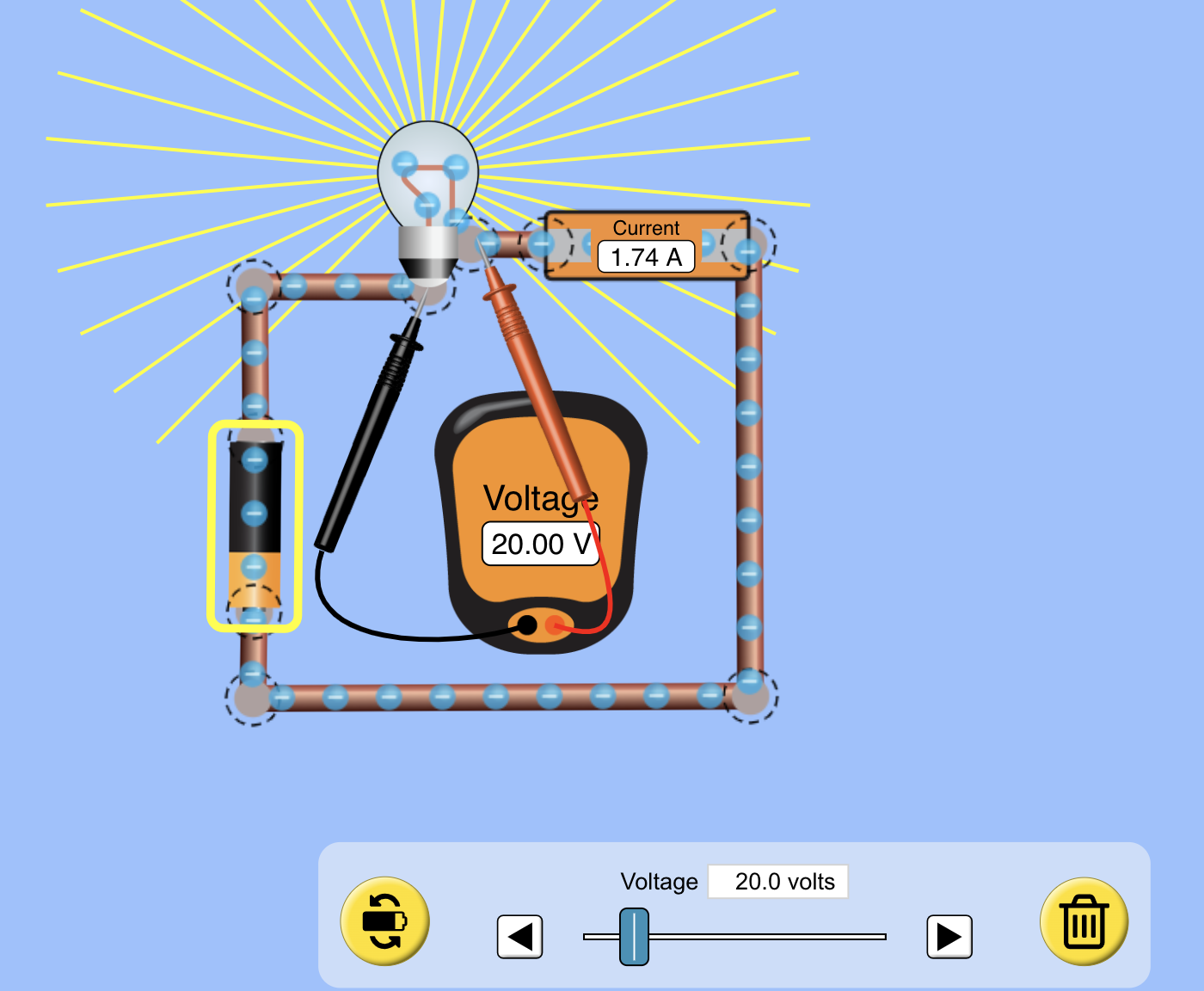
as the voltage across the light bulb is increased starting from zero. After you have made your prediction, again use the simulation: https://phet.colorado.edu/sims/html/circuit-construction-kit-dc/latest/circuit-construction-kit-dc_en.html Click on
Lab and construct the circuit. You can look at a picture of the correct
circuit here. Adjust the battery voltage in equal 5 volt steps by clicking once on the battery and adjusting
the slide switch, only this time, increase the resistance of the bulb by 0.5
ohm for each voltage step. Record the values in the table and sketch the
graph with a dashed line. See how the current through the bulb varies and
compare it to your prediction. Explain. Does
a light bulb obey Ohm’s law? How
would you find the resistance of the light bulb at any particular voltage? |
|
|
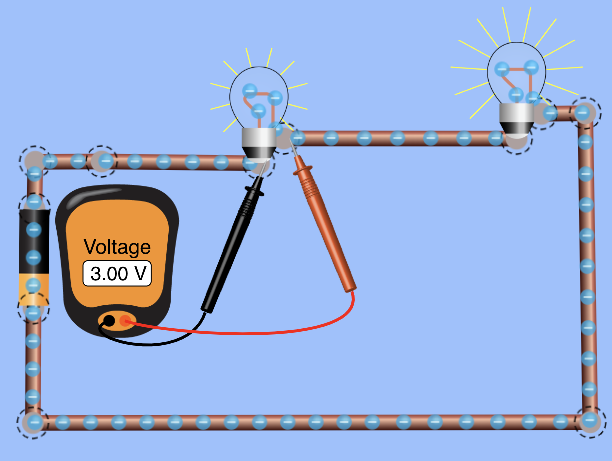
Demonstration 3: Two light bulbs are connected with the same potential difference
(voltage) across their terminals. Bulb 2 has twice the resistance of Bulb 1. Predict which bulb has a larger current flowing through it,
or do they both have the same current? Again use the simulation Construct
the same circuit as for Demonstration 2. Find the current for the two bulbs
with the same applied voltage. Compare these values to your prediction and
explain. Recall that the power delivered to a device is P = IV.
Predict which bulb has the larger power delivered to it, or do they both have
the same power? Which bulb is brighter, or are they both just as bright? Use the same simulation to explore your predictions.
Compare and explain. |
|
|
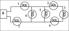
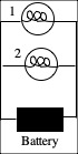
Demonstration 4: Seven bulbs are connected to a battery (B) as shown on the
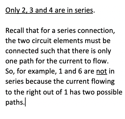
right. Define series connection, and list all combinations of
bulbs that are connected in series. After you have made your prediction, check the answer here. Was your
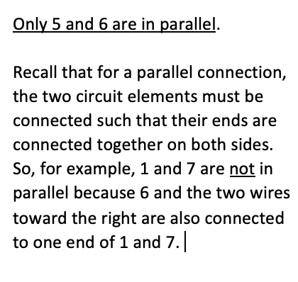
prediction correct? Why or why not? Define parallel connection, and list all combinations of
bulbs that are connected in parallel. After you have made your prediction, check the answer here. Was your
prediction correct? Why or why not? |
|
|
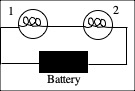
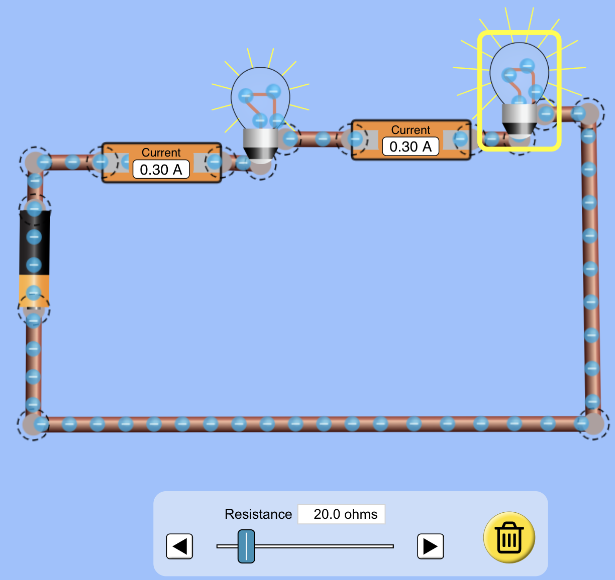
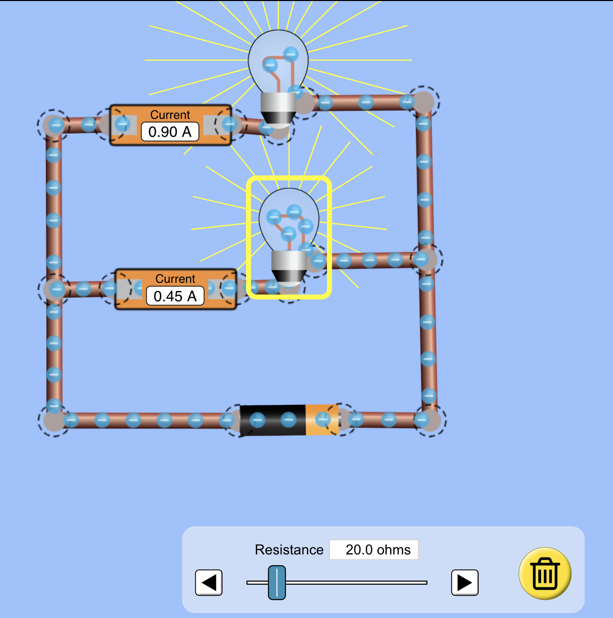
Demonstration 5: Two different
bulbs are connected to a battery as shown on the right. Bulb 1 has a smaller
resistance than Bulb 2. Predict the current through Bulb 1 as compared to the
current through Bulb 2. After you have made your porediction, use the same
simulation Construct
the circuit with two ammeters to measure the currents through Bulb 1 and Bulb
2. You can look at a picture of the correct circuit here.
Adjust the battery voltage to some non-zero value and observe the currents
through the two bulbs. Compare to your prediction and explain. Now
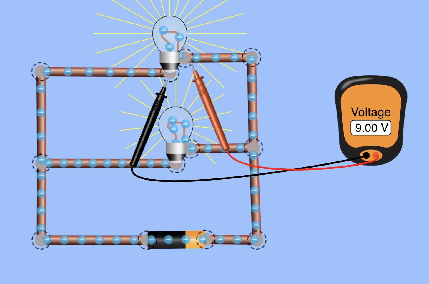
predict the voltage across Bulb 1 as compared to the voltage across Bulb 2. After you have made your porediction, use the same
simulation, removing the ammeters and adding a voltmeter first across Bulb 1
and then across Bulb 2. You
can look at a picture of the correct circuit with the voltmeter across Bulb 1
here. Adjust the battery voltage to some non-zero
value and observe the voltages across the two bulbs. Compare to your
prediction and explain. |
|
|
Demonstration 6: Two different
bulbs are connected to a battery as shown on the right. Bulb 1 has a smaller
resistance than Bulb 2. Predict the current through Bulb 1 as compared to the current
through Bulb 2. After you have made your porediction, use the same
simulation Construct
the circuit with two ammeters to measure the currents through Bulb 1 and Bulb
2. You can look at a picture of the correct circuit here.
Adjust the battery voltage to some non-zero value and observe the currents
through the two bulbs. Compare to your prediction and explain. Now predict the voltage across Bulb 1 as compared to the
voltage across Bulb 2, and also compared to the voltage of the batgtery. After you have made your porediction, use the same
simulation, removing the ammeters and adding a voltmeter first across Bulb 1,
then across Bulb 2 and finally across the battery. You can look at a picture of the
correct circuit with the voltmeter across Bulb 1 here.
Adjust the battery voltage to some non-zero value and observe the voltages
across the two bulbs, and across the battery. Compare to your prediction and
explain. |
|