
Digital Electronics
PHYS 432 - Spring 2020
Lab Kits
Updated Monday May 18, 2020
Introduction
This page will describe the parts in the take-home LabKit. There is also a walkthrough video of the kits on Canvas. This LabKit should contain everything you will need for the lab component of this class aside from a USB charger.
A few things that you might have that could also be useful are a set of angle cutters for trimming leads. Many of the parts (resistors and LEDs) have very long leads and if you trim them a bit shorter, it will make your breadboard a lot neater. You may also have a Digital Voltmeter available. You don't need this, but if you have one feel free to use it. Even in person, we use voltage probes a lot more than DVMs this quarter. Note that the cheap, Harbor Freight DVMs (which you can often get for free with a coupon) work fine as long as you don't need an accuracy better than around 0.1 V. Just put a decent battery in these before you start.
| Breadboard | 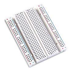 |
This is where we will build our circuits. These breadboards are half-height from even a standard compact breadboard, and they are definitely lower quality that the ones we have in the electronics lab. They were cheap enough that I could send one to each of you however. As these are small, being careful to not waste space will be important when laying out your circuits. |
|---|---|---|
| USB breakout | 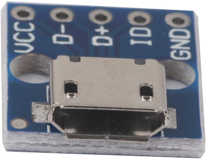 |
I have sent you a breakout for both micro-USB (shown) and the larger USB-A. This will be used to supply +5V to our breadboards. You will need to supply a USB charger or something similar and a cable to connect from the charger to one of these breakout boards. Please don't use your laptop for this, although a power bank battery could work fine. Watch the introduction video before trying to power your breadboard! |
| Integrated Circuits | There are 12 ICs provided. About half are standard 74XX logic gates (NAND, NOR, AND, XOR, INV) while the other half are more complex devices like multiplexers, decoders, counters, and flip flops. There are a variety of logic types including LS, HC, HCT, and so on. The actual number on the package will look something like 74LS00. A few of you have received CMOS NAND gates, as we ran out of TTL. So if you are missing a chip that says 7400 and have one that says TC40H000P, this is a NAND gate. It should work fine driving TTL chips. The inverter (7414) has Schmitt Trigger inputs, and we will use this to try to debounce a push button in Lab 4. The complete list is: 7400, 7402, 7408, 7414, 7447, 7473, 7474 (twice), 7486, 7490, 74138, and 74151. |
|
| LED assortment | 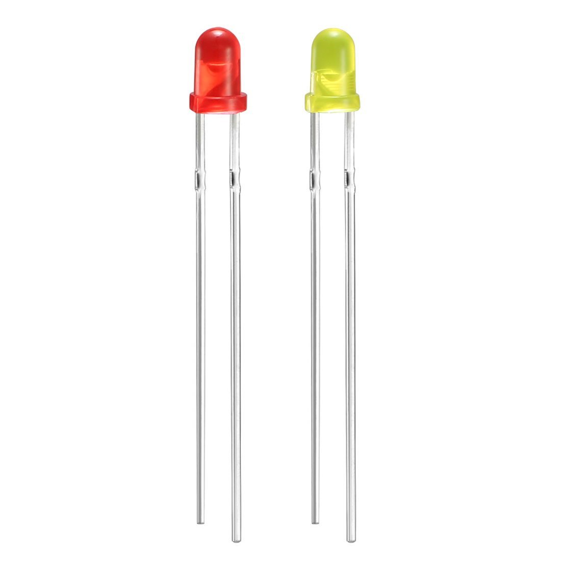 |
Blinking lights! In addition to looking good, these will be our main way to test the logic levels in our circuits. Caution: LEDs can only handle a small amount of current (around 10 mA). Never wire an LED directly to +5V, as they will almost certainly burn out. Always include a resistor in series with any LED. |
| Resistors | 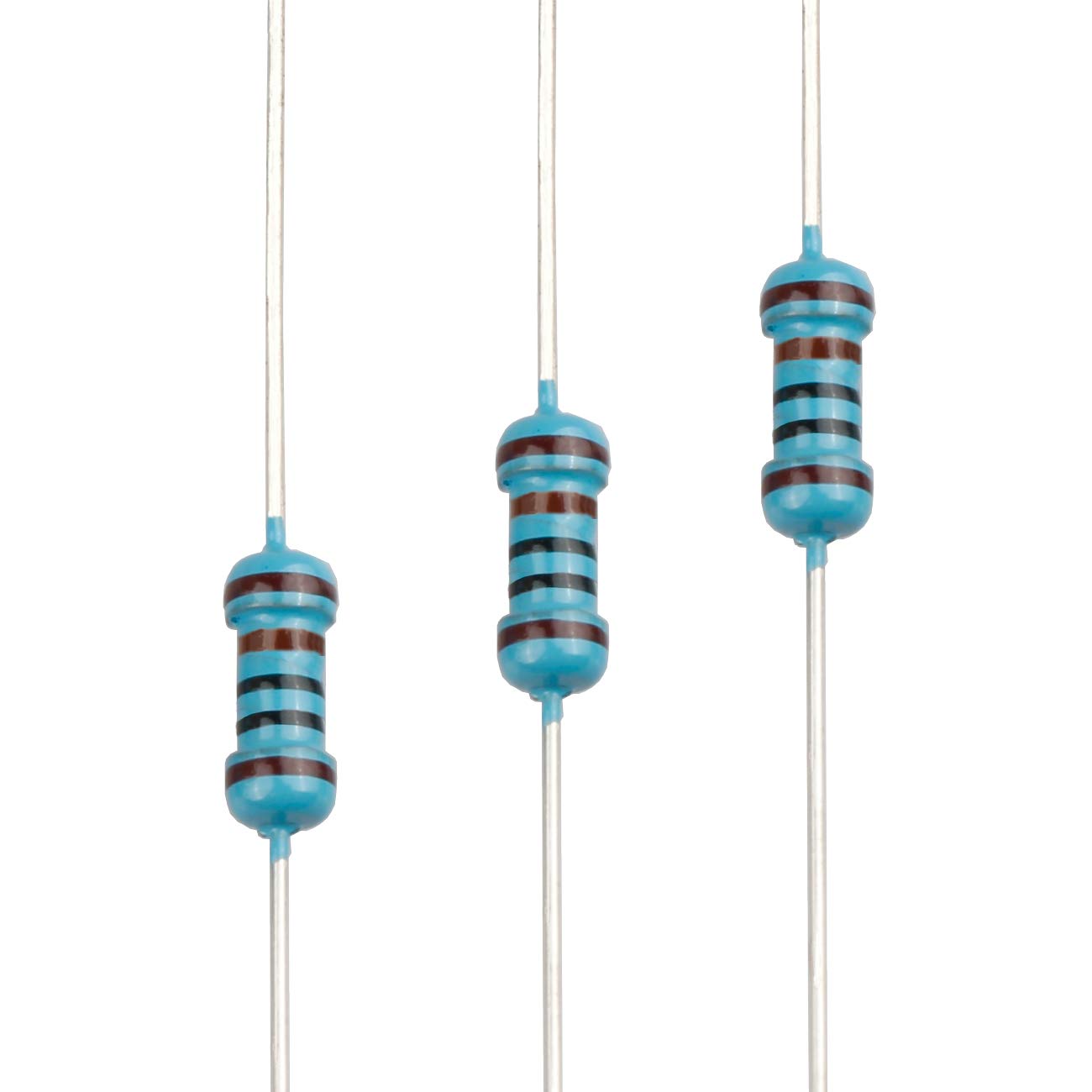 |
I have sent you lots of 1k resistors. These can be used for current limiting with LEDs, and also as pull-up resistors with buttons. I originally bought the smaller ones, and didn't like how fine the leads were. So I bought larger ones, which have nice leads, but now the resistor bodies are a bit large for sitting neatly on the breadboard. I sent you both, so you can decide which ones you prefer. The resistors still attached to the tape reels are 1k. The two additional loose resistors are 10k, and will be used with the NTC thermistor at the end of class. |
| Capacitors | 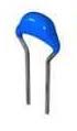 |
I have sent you a few different capacitors. The large black can is a 1 uF electrolytic that we will use in an RC circuit to try to stop switch bouncing. The flat green one is a 0.01 uF non-polar capacitor for bypassing the power leads of your ICs if they seem excessively noisy. I have also included two very small blue ceramic capacitors (shown in the picture) in the power rails of each breadboard. Just leave these in place. They are also bypass capacitors and will help keep noise out of the ICs. |
| 7-segment display | 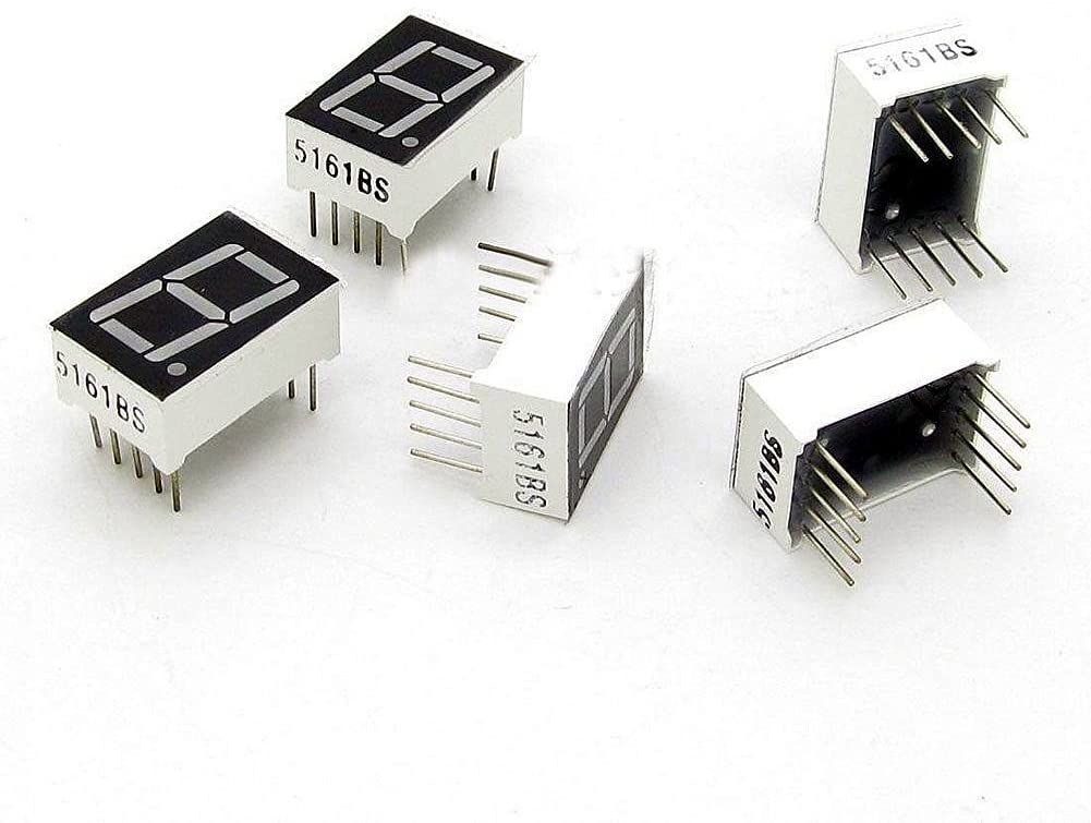 |
Old school display elements. Like any LED, never wire these up directly to a +5V supply. We will learn how to display numbers on these in the first lab. |
| Buttons |  |
More correctly known as a tactile switch, this normally-open (NO) switch can be used to create digital voltage levels. You have two of these, and I trimmed the leads to make them sit properly in the breadboard. |
| Switches | 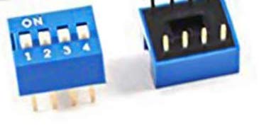 |
A single package with 4 dual-inline (DIP) switches. These single throw switches will make a connection between two opposing leads when the switch is in the on position. We will use these to generate 4-bit binary numbers. They should be inserted across the gutter of the breadboard just like an IC. |
| Potentiometer | 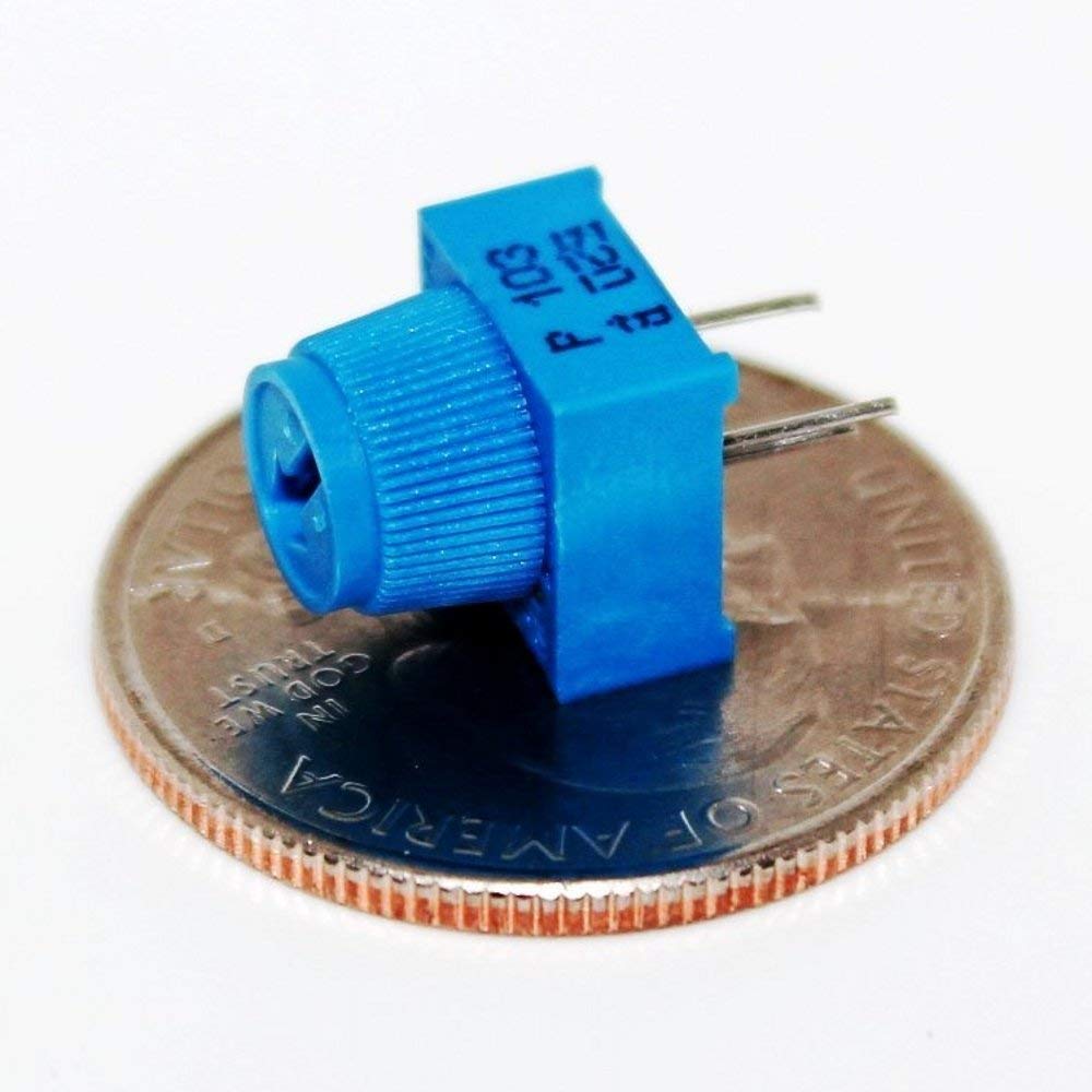 |
This 10k potentiometer will be used for various things when we need an adjustable voltage. The wiper is the middle pin. Make sure when you put these in your breadboard that each pin is inserted into a different breadboard row. |
| LED Tester | 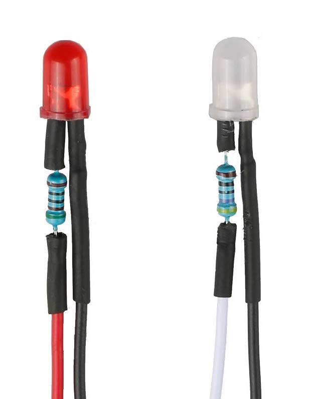 |
This is an LED with a current-limiting resistor soldered into one of the leads. I thought these would be great to make it easy to test for 5V on the breadboard, but the leads are a bit too small. I tried stripping a bit more of the insulation off on one of these, but the wire is stranded (not solid) so it doesn't push very well into the breadboards. These can still be handy to double check if you have HI or LO voltage somewhere, but I will probably use test leads and normal LEDs for most of my voltage testing. |
| Wires | 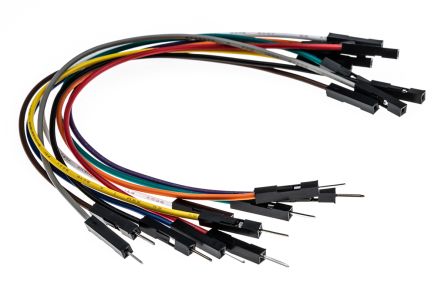 |
You have an assortment of wires (or leads) including an assortment of 10cm leads with pins on both ends for breadboards, along with a few with sockets that you can use to connect to the Arduino without having to put it in your breadboard. I have also sent along an assortment of short jumper wires. I would recommend that you use these jumpers to power your ICs and try to keep your breadboard a bit neater. The 10cm leads can make a real rats nest with some of our more complicated circuits. |
| Arduino Nano | 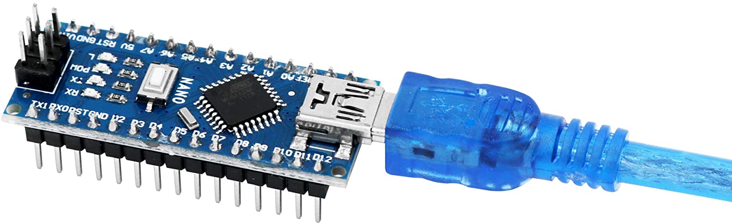 |
This is a breadboard-friendly microprocessor that we will use near the end of class instead of formal projects. Since the nano uses the odd mini-USB connector, I have provided this cable as well. Please don't try to put the Nano into your breadboard yet. It is very difficult to get them out, and easy to bend pins, so I would prefer that you only do this once. If you somehow destroy your Arduino, they are actually very cheap to replace. |
| LCD Dispaly |  |
2 row by 16 character LCD display with built-in Hitachi HD44780 display controller. This is an extremely common output device used with microprocessors, and we will control this using the Hitachi parallel interface. I have soldered pins onto these so they can be inserted into the breadboards. |
| Dual 7-segment Display | 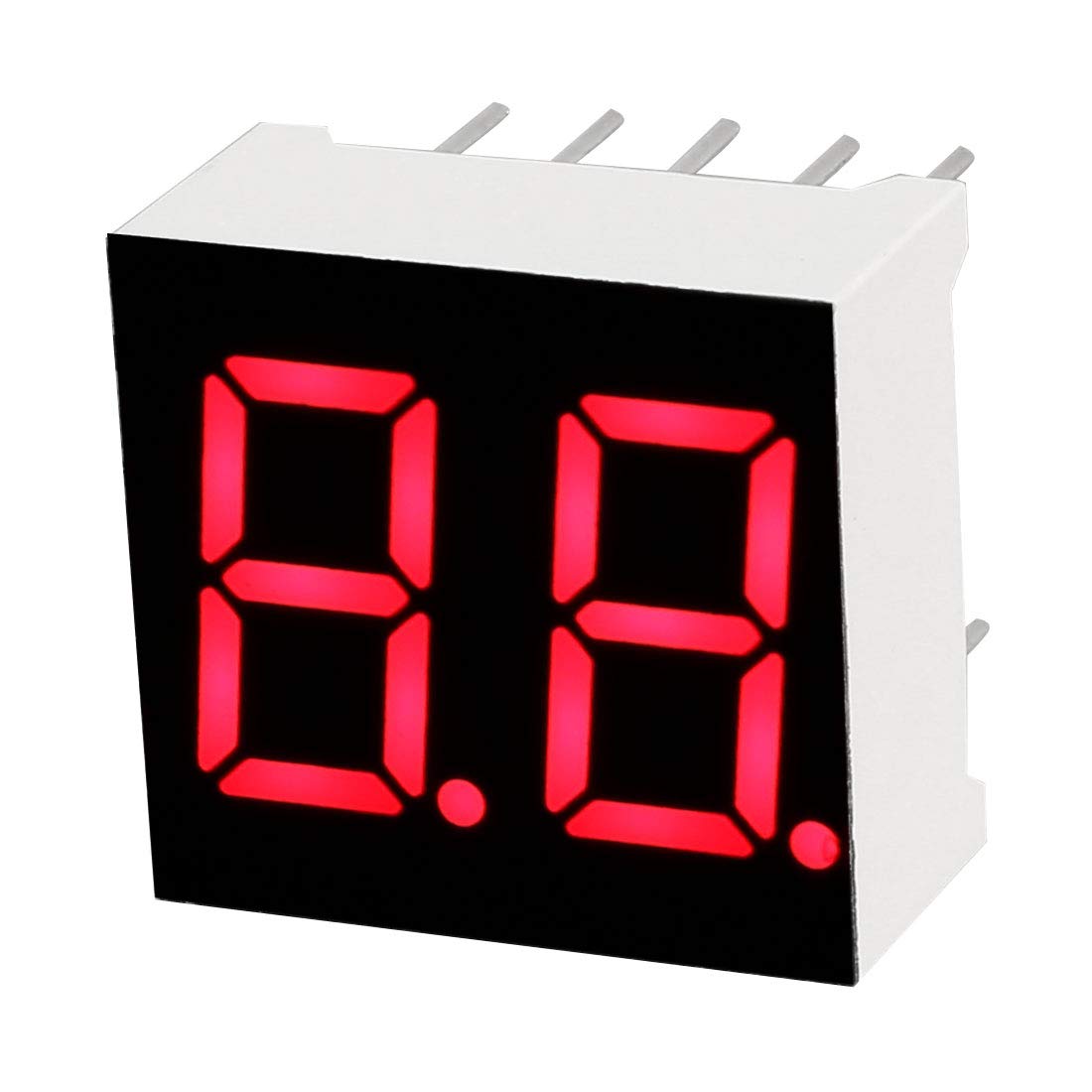 |
A two character common-anode seven segment display. This is for possible projects, and will require multiplexing with the Arduino to independently show both digits. |
| NTC Thermistor | 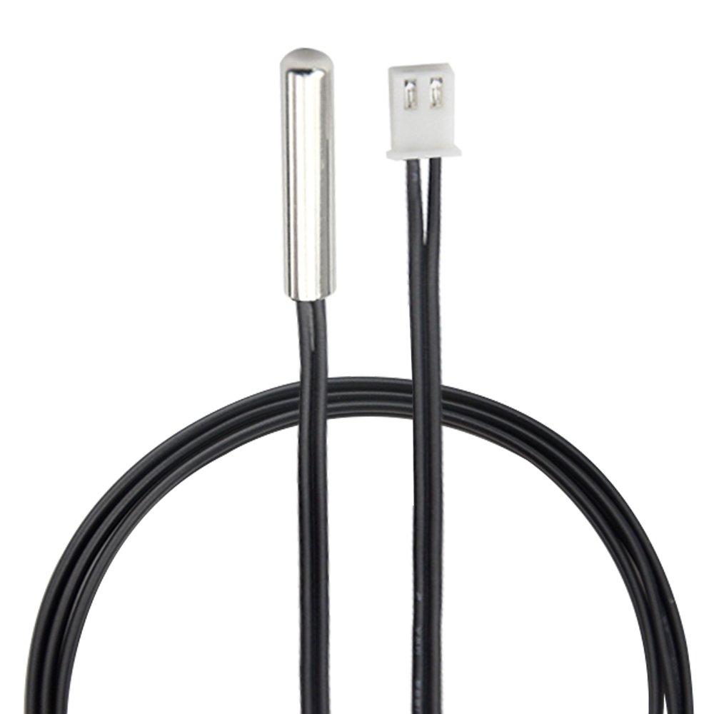 |
A negative temperature coefficient (NTC) thermistor. By measuring the resistance of this device with an ADC in the Arduino, we can make a temperature sensor. There is also a small, two-pin adapter to make it easier to plug this into the breadboard. |
| Three Color LED | 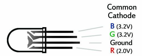 |
Three color LED, which is really three LEDs in one package. Controlling this from an Arduino makes it possible to create continuously changing rainbows, or even a visual display of temperature. |
| Foam | 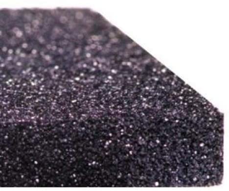 |
Anti-static foam for storing your ICs and other parts when not being used. |
|
|
Copyright © MMXX, Eric Torrence, All Rights Reserved |