|
|
|
|
Appendix A8: MGL0910 Magnetics and Gravity Processing on MGL0910
|
|
|
|
|
 | The magnetic field was recorded using a GeoMetrics 882 magnetometer towed nominally 100 meters astern of the vessel on starboard side. Data was logged to the LDEO data logging system. The system performed well during the survey. Approximately 1,380,000 points of data were collected.
|
|
|
|
|
|
| Instrument: GeoMetrics 882 Cesium Marine Magnetometer System Specifications
|
|
|
|
|
|
| Operating Principle: Self-oscillating split-beam Cesium Vapor (non-radioactive)
|
|
|
|
|
|
| Operating Range: 20,000 to 100,000 nT
|
|
|
|
|
|
| Operating Zones: The earth’s field vector should be at an angle greater than 6° from the sensor’s equator and greater than 6° away from the sensor’s long axis. Automatic hemisphere switching is standard.
|
|
|
|
|
|
| CM-221 Counter Sensitivity: <0.004 (nT/πHz) rms. Up to 10 samples per second
|
|
|
|
|
|
| Heading Error: ∀1 nT (over entire 360° equatorial and polar spin )
|
|
|
|
|
|
| Absolute Accuracy: <3 nT throughout range
|
|
|
|
|
|
| Output: RS-232 at 1,200 to 19,200 Baud
|
|
|
|
|
|
| Mechanical: Sensor Fish: Body 2.75 in. (7 cm) dia., 4.5 ft (1.37 m) long with fin assembly (11 in. cross width), 40 lbs. (18 kg) Includes Sensor and Electronics and 1 main weight. Additional collar weights are 14lbs (6.4kg) each, total of 5 capable
|
|
|
|
|
|
| Tow Cable: Kevlar Reinforced multiconductor tow cable. Breaking strength 3,600 lbs, 0.48 in OD, 200 ft maximum. Weighs 17 lbs (7.7 kg) with terminations.
|
|
|
|
|
|
| Operating Temperature: -30°F to +122°F (-35°C to +50°C)
|
|
|
|
|
|
| Storage Temperature: -48°F to +158°F (-45°C to +70°C)
|
|
|
|
|
|
| Quality Control: All data logged was checked for dropped scans and the time difference between each sample logged was measured using LDEO program “checktimes_rev.pl” .
|
|
|
|
|
|
| Reference field: International Geomagnetic Reference Field 2005 (IGRF 2005) model of main field at 2005.0 and a predictive model of the secular variation for adjusting to dates between 2005.0 and 2010.0.
|
|
|
|
|
|
| Residual field: Magnetic declination for the survey area was 16.42 degrees.
|
|
|
|
|
|
| Navigation: Magnetic data was merged with CNav navigation data (latitude/longitude) using LDEO program “magNavMerge.pl”.
|
|
|
|
|
|
| Final data: Data set contains the navigation positions with the total field readings in one-second intervals matched to the navigation GPS time stamp at the nearest +/- second.
|
|
|
|
|
|
| The gravity field was recorded using a Bell Aerospace BGM-3 marine gravimeter. Reference document “MGL0910_Offsets” contains the XYZ of the sensor relative to the NRP (navigation reference point of the vessel where the DGPS navigation system positions are resolved). Approximately 2,592,000 points of data were collected in the survey area. Performance of the BGM-3 was considered consistent and nominal.
|
|
|
|
|
|
| Instrument Detail: Instrument: Bell Aerospace BGM-3 Marine Gravity Meter
|
|
|
|
|
|
| Logging: Data is output at 1-second intervals and logged on LDEO logger system.
|
|
|
|
|
|
| Calibration: See attached calibration sheet (attachment 8) dated 03/30/2004.
|
|
|
|
|
|
| Quality Control: All data logged was checked for dropped scans using LDEO program “checktimes_rev” (Attachment 1).
|
|
|
|
|
|
| Observed gravity value in mGals is calculated by filtering the raw 1-second counts with a 360-second Gaussian filter, scaling the results and adding a bias. The data set is then merged with the navigation attributes, latitude, longitude, course, and velocity matched using the GPS time stamp +/- second. Eotvos correction is then applied to the data set. Data plots are generated and visually checked to determine satisfactory Eotvos corrections. Data spikes caused by turns and other anomalies are deleted from the data set. Free-air anomaly (FAA) is then calculated on the data set. Final data set is then decimated to one-minute data samples.
|
|
|
|
|
|
| At time of cruise completion the product that is available is the raw data only. The scripts necessary to reduce the data are still in development. The process of updating and certifying the programs used on the R/V Ewing to be compatible with the hardware of the R/V Langseth is anticipated to take one month from 9/20/2009 and is being done by Anthony Johnson and David Martinson. The following describes the final product that will be provided by the LDEO science support team.
|
|
|
|
|
|
| Quality Control: The time difference between each sample logged is measured using LDEO program “checktimes_rev” .
|
|
|
|
|
|
| Navigation: The CNav NMEA output (logged to LDEO logger at 1 second intervals) is parsed using LDEO program “cnav” to extract and format the following attributes: latitude, longitude, course, and velocity (in knots). The script output string is then filtered with a five point running average” using a Perl script.
|
|
|
|
|
|
| Merge: The “filtered” gravity file and the “filtered” navigation and velocity file are then merged using a Perl script. The merge script uses the navigation GPS time stamp for data point matching, matching to the nearest tenth of a second.
|
|
|
|
|
|
| Eotvos Correction: The Eotvos reduction procedure corrects for artificial gravity effects due to changes in ships course and speed:
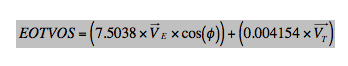
where VT is ship speed in knots, VE is the eastward component of the velocity, and φ is the degrees in latitude. These velocities were derived from a smoothed GPS navigation using LDEO developed scripts.
|
|
|
|
|
|
| Base Station Description: A gravity tie was performed in Astoria, Oregon 8/21/09 at an absolute gravity tie point prior to departure for the survey using a LaCoste Romberg G portable gravimeter by LDEO science personnel. A second gravity tie was done in Astoria on 9/19/09 at the conclusion of the survey.
|
|
|
|
|
|
| DC shift: The initial DC shift calculated on 8/21/09 is 0.21 mGals. The final DC shift calculated on 9/20/09 is -0.21 mGals. The measured drift is 0.014 mGals per day. Potsdam correction was removed from the Absolute tie point value as the BGM 3 outputs uncorrected gravity values.
|
|
|
|
|
|
| Free-Air Anomaly: The Free Air Anomaly (FAA) reduces the raw data by removing the gravitational effect of the reference ellipsoid. This will be done using an LDEO program. The FAA was also corrected for a regional field based on the 1987 International Gravity Formula (IGF):
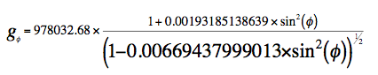
where the symbol g represents the absolute gravity value. The angle is the latitude in degrees.
|
|
|
|
|
|
| Historical note: Earlier cruises have used the 1980, 1967 and 1930 gravity formula in calculating the FAA. Since these all differ by a constant, it is necessary to check the formula used in a particular survey prior to merging the data with this current survey.
|
|
|
|
 |
|
|
| The above in Word format: MGL_Grav&MAG.docx
|
|
|
|
|
|
| RV Langseth Sensor configration is described in Appendix A9: MGL0910 RV Langseth Sensor Configuration and Data Formats
|
|
|
|
|
|
 | MGL0910 Gravity Ties and Gravimeter calibration
|
|
|
|
|
|
|
| MGL GravTie 2009-08-21.pdf
|
|
|
|
 |
|
|
| MGL GravTie 2009-8-21.doc
|
|
|
|
 |
|
|
| MGL GravTie 2009-9-19.doc
|
|
|
|
|
|
|
| BMG Calibration Sheets 2004-3-30.pdf
|
|
|
|
|
|
| Perl routines used in on-board magnetics and gravity processing
|
|
|
|
|