
Digital Electronics
PHYS 432 - Buttons and Lights
Updated Wednesday May 05, 2021Introduction
This is the first task in the Arduino project. This assumes you have already set up the Arduino IDE and tested your board. If you have not, do so now!
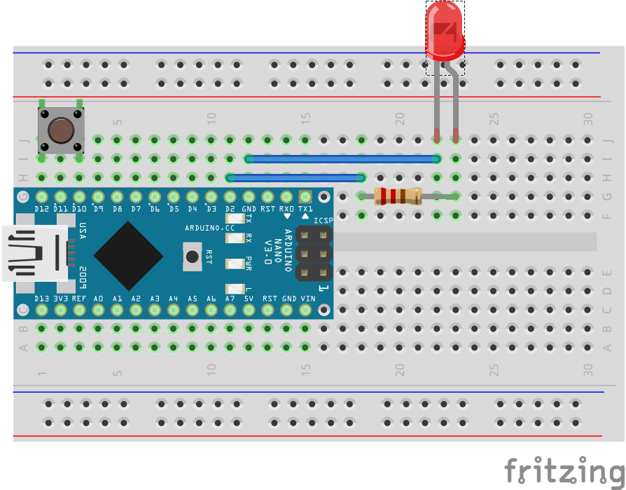
This task will introduce simple digital input and output (I/O) with a button and an LED. The first step is to put your Nano into your breadboard. Check the wiring diagram below and try to put the Nano in exactly this position. As space on our breadboard is in short supply, it is important to place the Arduino at the very end of the breadboard with the USB connection accessible. Inserting the Arduino takes a fair amount of force, and removing it is even more difficult, so we only want to do this once. When inserting the board, try to push on the edges of the board, and don't apply force to the ATMega chip itself.
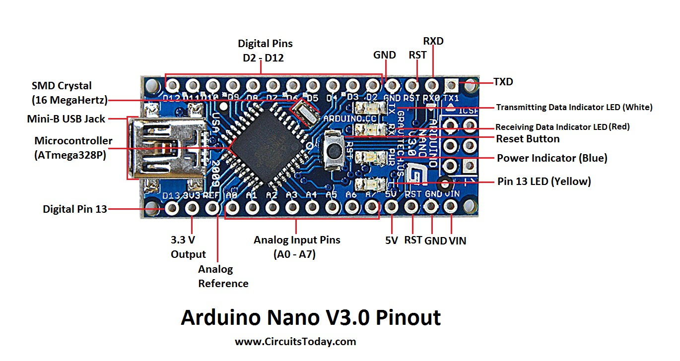
To orient yourself to the available pins, look at the figure below. Click on any image to get a larger-scale view. The pins labelled +5V, +3.3V, and GND provide regulated voltages which can be used to power other components. The VIN pin is primarily used to supply power from an external source (like a battery) and feeds a voltage regulator, so anything from 7-12 V input works. When running from USB power, this is connected directly to the regulated 5V USB power line, so it will also appear to supply +5 V. For this lab, we will be using the digital I/O pins labelled D2-D12 on the right side of the board. Analog inputs A0-A7 are present on the left side of the board. On many boards, these can also be used for digital I/O if needed, but this isn't possible with the Nano. Many pins have secondary functions, but we don't need to worry about that for now.
Wiring
We will use one button and one LED to test the digital I/O of the Arduino. Wire up the circuit shown below. The switch goes between D10 and D12 (it is shown in the figure below as a 4-lead switch, but ours only have 2 leads). The LED is connected between D2 and ground with a 1k current-limiting resistor in series. If you prefer to set up a ground rail, you can do that also by connecting the GND pin to one of the rails. I would recommend not wiring up a +5V rail, as this voltage is directly supplied by your USB connection. If you accidentally short this rail to ground, you could damage your USB port, although if you are careful this will work fine. We will mostly use +5V provided by the digital I/O pins, which have an upper current limit of around 100 mA, and if sorted will at worst will burn out a pin on the Arduino itself.
Sketch
Put the following sketch into the Arduino IDE or else download it from task1.ino. All sketches have two top-level functions, setup() and loop(). You may not be surprised to learn that setup() is called once when the Arduino powers up (or resets) and is intended for initialization that only needs to be done once, while loop() is continuously called as the processor is powered. Note that in C (really C++) syntax, anything on a single line after a double slash is ignored, and everything between /* and */ on multiple lines is ignored. These are comment characters, and it is good practice to provide lots of descriptive comments in your code.
/*
 * Task1
 *
 * Uses a button with weak pull-up to light up an external LED
 *
 */

// Good practice to define pin numbers by logical meaning
#define LED_PIN 2
#define BUTTON_IN 10
#define BUTTON_GND 12

void setup() {
  // Pin to control LED
  pinMode(LED_PIN, OUTPUT);
  digitalWrite(LED_PIN, LOW);    // Start with LED off

  // Pin to provide GND side of button
  pinMode(BUTTON_GND, OUTPUT);
  digitalWrite(BUTTON_GND, LOW); // Always LO (ground)

  // Pin to read button state, use internal pull-up to avoid external resistor
  // This also emulates TTL inputs that float HI.
  // Use INPUT for normal digital input (emulates CMOS input)
  pinMode(BUTTON_IN, INPUT_PULLUP);
}

void loop() {
  // Test the button state
  // As this is negative true (LO when pressed), invert the return value with !
  bool buttonPressed = !digitalRead(BUTTON_IN);

  // Light up the LED if the button is pressed
  // by writing the boolean (HI/LO) to the output pin
  digitalWrite(LED_PIN, buttonPressed);
}
How it Works
In the setup() block, we do everything that we only want to do once. In this case, that means defining which pins are input and output using pinMode() and also writing some specific voltage levels to the output pins using digitalWrite(). It is often handy to digital output pins to supply +5V or ground by setting these to be HIGH or LOW. This technique also provides some safety, as these pins can typically only source or sink 100 mA or less.
Once a voltage is written to an output pin, it stays there until changed. At a low level, the pin values are set by the processor writing a specific bit pattern (one bit per pin) to a special memory address that is interfaced to the physical pins. Reading the values is as simple as reading the bits from this same address. Setting the input or output direction involves writing to a separate tristate register that controls whether the output circuitry is connected to the physical pin or not.
In the loop() block, we read the voltage on the pin with the internally-connected pull-up resistor. In this way, if the button is not pressed, the pin will read HIGH while pressing the button will make a connection to ground and it will read LOW. The Arduino code will interpret HIGH as boolean True, so to provide the proper assertion-level meaning to the buttonPressed variable, we invert the return value of the function with the exclamation point (or bang). To see more of the Arduino syntax (which is basically C, but also used in python) see the Language Reference. One plus of C syntax is that unlike in python, the spacing and indenting of your code is irrelevant (the compiler completely ignores this). The tradeoff is that all statements must be terminated with a semicolon. You can actually put multiple statements on the same line (as long as each is ended with a semicolon) but don't do this as it makes you look like a rube.
This code is very simple, because this loop will just continuously execute as long as the board has power. The button is read, and if the button is pressed, the LED lights up.
Compiling and Uploading
Follow the same procedure described on the Arduino IDE page to compile and upload your sketch. It is always worth noting how much resource your sketch will use on the chip, and in this case you should see very small numbers (3% of program space, 0% of dynamic memory). If you have any errors either in the compilation step or uploading, you need to debug this before finishing.
If everything uploaded without error, your Arduino should now be running your program. Press your button and see if the LED lights up. If it doesn't, it is most likely that you have your LED in backwards. If your LED lights when the button is pressed, congratulations! You now have the ability to read and write digital values!
Going Further
While not necessary, it is interesting to think about the code needed to do more complicated things. One example would be to have the LED flash for 0.5s each time the button is pressed. This should be easy to implement with some if statements and some wait() commands. Usually, calling wait() is bad practice, as the processor can't do anything else during this time, but if all you are doing is lighting up an LED, there is no reason not to just use wait. The simplest solution is to just light the LED, wait 500 milliseconds, then turn it back off. If you just hold the button down, however, it will just remain lit. Think about what else you might need to check that the button is released. You may find the while condition to be useful.
When you are done playing around, save your sketch somewhere you can find it, and move on to Task 2.
|
|
Copyright © MMXX, Eric Torrence, All Rights Reserved |