
Digital Electronics
PHYS 432 - Button Debouncing
Updated Wednesday May 05, 2021Introduction
This optional task shows how to debounce buttons in software on the Arduino. This method avoids needing to implement any additional debouncing circuitry, and is very convenient to implement in most cases. This lab will also introduce the concept of hardware interrupts in the Arduino. A full discussion of interrupts is beyond the scope of this page, but we will introduce a simple example of in interrupt to detect when a pin voltage has changed. Most "real" microprocessor code makes extensive use of different interrupts to control timing and to avoid slowing down the event loop constantly checking for things to change. Many of the built-in Arduino commands also use timer interrupts to efficiently perform tasks with critical timing constraints.
Wiring
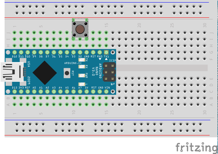
This task has a very straightforward wiring diagram. A single tactile switch is connected between digital pin 3 and ground. Hardware interrupts require additional circuitry within the Arduino to function, and not all pins on all devices have this capability. For the Nano, only pins 2 and 3 can generate interrupts on changing voltage values, so we will use pin 3 here.
Non-debounced Sketch
Put the following sketch into the Arduino IDE or else download it from task5a.ino. This sketch does not debounce the button, and is intended to demonstrate the problem of button bouncing on the Arduino.
/*
 * Task5a
 *
 * Demonstrate using an interrupt routine to detect a button press
 *
 * This example is *not* debounced
 *
 */

#define BUTTON_IN 3

// Any variable used in an interrupt routine must be declared as volitile
// This ensures the compiler reads the value directly from dynamic memory (RAM)
// and not a cached register location.
volatile int nButton=0;

// the setup function runs once when you press reset or power the board
void setup() {

  // Pin to read button state, use internal pull-up to avoid external resistor
  // This also emulates TTL inputs that float HI.
  // Use INPUT for normal digital input (emulates CMOS input)
  pinMode(BUTTON_IN, INPUT_PULLUP);

  // initialize serial communication at 9600 bits per second:
  Serial.begin(9600);

  // Write something out to show we are alive
  Serial.println(F("Starting..."));

  // Setup the interrupt handler on pin change
  // Must be attached to pin 2 or 3 on Nano
  // FALLING generates an interrupt on falling edge
  attachInterrupt(digitalPinToInterrupt(BUTTON_IN), countButton, FALLING);
}

// the loop function runs over and over again forever
void loop() {

  Serial.print(F("The button has been pressed "));
  Serial.print(String(nButton));
  if (nButton==1) {
    Serial.println(F(" time"));
  }
  else {
    Serial.println(F(" times"));
  }

  // Wait 1 second so we don't flood the serial port
  delay(1000);
}

// This function is called via the interrupt handler
// every time a falling edge is detected on pin 3.
// This can happen at any time and will suspend the normal program execution
// until this routine finishes.
void countButton() {

  // Increment our button count
  // Any variable used to communicate information with the
  // rest of the code must be declared at global scope and
  // use the volatile declaration.
   ++nButton;

  // Keep interrupt routine as short as possible.
  // Do any real work in the event loop.
}
How it Works
An interrupt can be registered for a wide range of hardware actions. Here, we use attachInterrupt to instruct the Arduino to automatically call the countButton routine any time the voltage level on pin 3 makes a transition from HI to LO. Other possible pin interrupts are CHANGE, HIGH, and LOW. Interrupts are useful, because they can avoid the main program waisting time constantly checking (or polling) for changes in input values, and they are sensitive to short pulses that you might miss with polling. When the interrupt happens, the normal program execution is suspended, and the indicated interrupt routine starts executing instead. While the interrupt handler is active, further interrupts from other systems will be registered, but they can not be handled until the current routine finishes. As a result, it is best practice to keep the amount of code in the interrupt routine as short as possible. Here the interrupt will count the number of times a falling edge is seen on an input pin, even if this happens while the delay() function is executing. As a result, we shouldn't miss any button presses using this technique.
In this code, we are just counting how often a falling edge is observed, and printing that result to the serial port every second. This design avoids flooding the serial port with messages, and reduces any interference between the button interrupts and the timer interrupts used to control the serial port communications.
Compiling and Uploading
Follow the same procedure described on the Arduino IDE page to compile and upload your sketch. Play around with pressing your button to see how well (or not) this works. Try different things, including pressing the button quickly, pressing slowly and deliberately, and even holding the button down and wiggling your finger back and forth. I found I could produce many more than one falling edge for almost anything I did with the button. Our tactile switches are particularly noisy, so for any application where counting the number of presses accurately is important (as opposed to just lighting up an LED), some method of debouncing is needed.
Debounced Sketch
Put the following sketch into the Arduino IDE or else download it from task5b.ino. This sketch uses an interrupt and a shift-register style state machine to debounce the button. I spent quite a bit of time fiddling with different techniques to get good performance, and this was by far the best performing of the various things I tried. Debouncing is always a tradeoff between fast response and false positives, and this routine was really optimized for speed.
/*
 * Task5
 *
 * Demonstrate using an interrupt routine to detect a button press.
 * This code does debounce the button.
 *
 */

// Pin to read for button value
#define BUTTON_IN 3

// Boolean to show if pin value has changed
// Because this value is changed in the interrupt, must declare as volatile,
// which tells the compiler to always read this from memory, not a register
volatile bool pinChange; // Communicates from interrupt routine

// the setup function runs once when you press reset or power the board
void setup() {

  // Pin to read button state, use internal pull-up to avoid external resistor
  // This also emulates TTL inputs that float HI.
  // Use INPUT for normal digital input (emulates CMOS input)
  pinMode(BUTTON_IN, INPUT_PULLUP);

  // initialize serial communication at 9600 bits per second:
  Serial.begin(9600);

  // Write something out to show we are alive
  Serial.println(F("Starting..."));

  // Setup the interrupt handler on pin change
  // Must be attached to pin 2 or 3 on Nano
  attachInterrupt(digitalPinToInterrupt(BUTTON_IN), pinChangeRoutine, CHANGE);
}

// the loop function runs over and over again forever
void loop() {

  // Count how many times the button has been pressed
  // static means this is not reinitialized every loop
  static unsigned int nButton=0;

  // Previous button state (to find changes)
  static bool lastState;

  // Get the logical button value (pressed = true) from debounce routine
  bool buttonValue = buttonState();

  // Has this changed?
  if (lastState != buttonValue) {
    lastState = buttonValue;  // Update last state

    // If it is now pressed, increment counter and print result
    if (buttonValue) {
      ++nButton;

      Serial.print(F(" The button has been pressed "));
      Serial.print(String(nButton));
      if (nButton==1) {
        Serial.println(F(" time"));
      }
      else {
        Serial.println(F(" times"));
      }
    }
  }
}

// Interrupt handler, this is called via the interrupt handler every
// time a change is detected on the button pin.  Best to do very little here.
void pinChangeRoutine() {
  pinChange = true;
}

// Debounce routine, returns best guess of button state
bool buttonState() {

  // 8-bit storage used as shift register of past pin values
  static byte pinHistory = 0;

  // Best guess of debounced button value
  static bool buttonValue = false;

  // Time (in ms) since Arduino rebooted
  static unsigned long lastTime = 0;

  // If no change, just return last value
  if (!pinChange) return buttonValue;

  // Check how long since we last read the pin
  unsigned long currentTime = millis();
  if ((currentTime - lastTime) < 4) return buttonValue;
  lastTime = currentTime;

  // Read the pin and push value onto buttonHistory
  pinHistory = (pinHistory<<1);
  if (digitalRead(BUTTON_IN)) bitSet(pinHistory, 0);

  // If the value has been stable for the last 8 x 4ms = 32ms, consider it stable
  // buttonValue reflects whether the button is pressed (true) or not (false)
  if (pinHistory == 0xFF) {
    buttonValue = false;
    pinChange = false;  // Reset this to indicate we are in a stable state
  }
  if (pinHistory == 0x00) {
    buttonValue = true;
    pinChange = false;
  }
  return buttonValue;
}
How it Works
We now use a CHANGE interrupt, as we want to see both when the button is pressed and when it is released. The interrupt just sets a boolean that is used in the main loop() to indicate something has happened with the pin. The butttonState routine implements a kind of state machine. It has a dedicated bool buttonValue (declared static so that it doesn't lose the result when the routine returns) with the desired button state, and an 8-bit value pinHistory that is being used as a shift register to keep track of the pin voltage history. This routine uses the very handy millis() routine that returns the number of milliseconds since the Arduino was last reset. By remembering the last time this was called, we can sample the pin voltage every 4 ms and keep track of the history. There is also a micros() routine that can measure times with sub-millisecond precision, although eventually this is limited by the microprocessor clock speed.
This routine will only recognize the button in a new state if it has been stable for the last 8 readings, which implies a 32 ms lag between when the button is first pressed, and when the code will recognize it as being in a new state. With a bit of extra code, I could have made it change on the first transition, but this slight delay seemed acceptable. The buttonValue variable represents the assertion-level logic of whether the button is pressed, which is inverted from the voltage levels on the actual pin. Finally, the pinChange boolean is set back to false when a stable value has been observed, which will cause the routine to just return buttonValue until the next interrupt happens.
Compiling and Uploading
Follow the same procedure described on the Arduino IDE page to compile and upload your sketch. Now see if you can make the button bounce. Instead of counting presses and writing this every second, this code now outputs a message every time the button is pressed. While I could still occasionally make this bounce, I could not push the button fast enough for it to obviously miss any button presses. Making the stable time longer further reduced any chance of bouncing, but with delays much longer than 30 ms, I could start to see fast toggling of the button being missed.
Going Further
One of the benefits of using interrupts is that it frees up the processor to do other things and doesn't require constant polling to detect changes on the input lines. One thing that you can do is put the processor to sleep (shutting down the internal clock and other circuitry) to reduce power. This can be critical for battery-powered designs, as the ATmega will draw around 20 mA when running, but during sleep can draw under 1 microamp. An interrupt will wake the processor from sleep, so if you only have the processor running when there is something to do, it can save a considerable amount of power. On the Nano board, there are other chips (not to mention the power LED) that draw power and can not be shut off, so this particular board isn't so suitable for low power applications, but other variants of the Arduino board can work well. There are a number of examples of putting an Arduino to sleep, and also a number of different sleep modes to choose from. An accessible discussion of sleep modes can be found here. You could try this out and see if you can shut down the chip while waiting for interrupts. Note that it takes some time for the processor to recover from being shut down, and I was not able to detect absolutely all button presses when using the power down mode, as I could press the button a second time before the processor could wake up and clear the first interrupt.
To better understand the button bouncing problem, I built a rudimentary logic probe sketch that used micros() to count the time between successive pin changes. To avoid repeated calls to Serial slowing things down, I stored these times into an array inside the interrupt routine, and printed it out every second to see what had happened. You could try something similar. I found that there were often bounces around 100 microseconds, but occasionally there would be a flurry of bouncing that could last 30 ms or more. This is why my solution uses a relatively large number of samples (8) to ensure the button has settled. You could probably just count how long it has been since the last pin change, require this to be over 30 ms, and then read the pin voltage. You should try your own hand at this problem and see how well you can do. As an interesting aside, the millis() and micros() routines won't update inside an interrupt routine, as they involve some processor code of their own, but they will give the value at the time the interrupt routine was entered.
|
|
Copyright © MMXX, Eric Torrence, All Rights Reserved |