
Digital Electronics
PHYS 432 - Liquid Crystal Display
Updated Wednesday May 05, 2021Introduction
This task shows how to interface an Arduino Nano to a 2x16 LCD display driven by the popular Hitachi HD44780 controller. A wide range of LCD displays use this controller, and the Arduino libraries used in this task work with all of them. Here we will use a 4-bit parallel interface to send commands to the LCD board. You can also find boards with additional circuitry to allow control over popular serial bus protocols such as SPI and I2C. Being able to write to a local display is always more satisfying then sending data back to your computer over the serial port. Mastering the display interface allows you to think about building truly stand-alone devices that can run from a USB charger or battery pack, and do not need to be tethered to your computer. There are a large number of tutorials discussing a LCD display interfacing to the Arduino. One of the better ones I have found, and was a source of motivation for this task, is this tutorial. For the gory details about the Hitachi HD44780 controller, you can look at the Wikipedia page or download the 60 page manual here.
Wiring
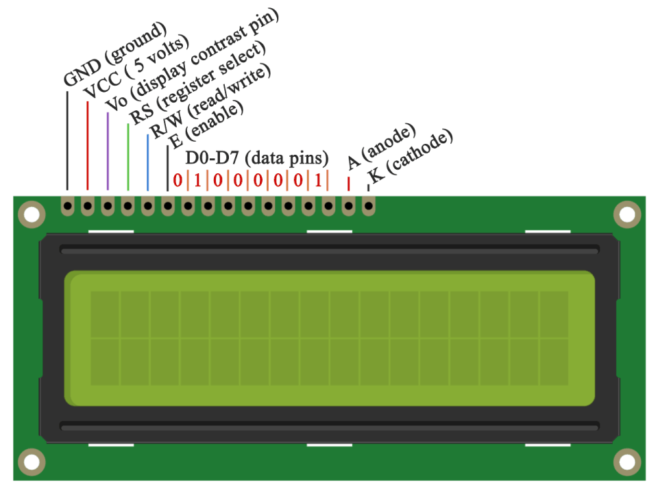
This task has the most complicated wiring of any project we have tackled. The LCD display has 16 pins as shown below. There are 5 pins dedicated to power, 3 control lines, and 8 data lines. We will briefly describe the functionality of each pin, but you should look at the tutorial linked above for a more complete discussion. Starting from Pin 1, we have Vss (ground) and Vdd (+5V). These provide the power for the digital logic. The next pin, V0, sets the display contrast. You can probably get away with connecting this to +5V, but we will use a potentiometer to ensure we can see the characters. The next three pins are control lines. All but read/write will be connected to the Arduino so that we can manipulate these as needed. The R/W line will be grounded which means we will only write to the display. The next 8 pins are data lines used to write 8-bit characters to the display. We will use a 4-bit mode where each byte is sent in 2 separate chunks (nibbles) at a time. This saves 4 wire connections. The final two pins are the Anode (A) and Cathode (K) of the electroluminescent backlight. The anode should be attached to +5V and the cathode to ground.
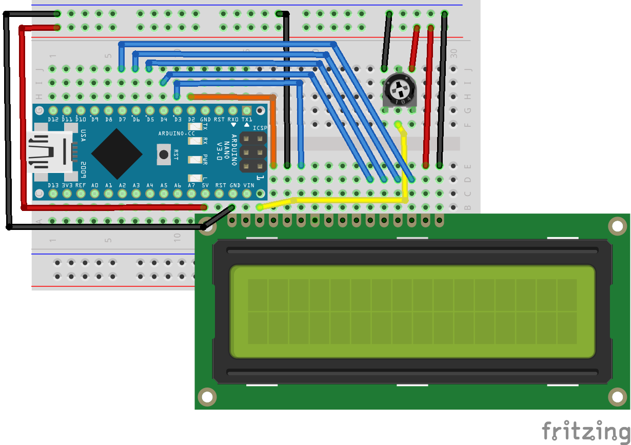
To get the Nano and LCD board to fit, you must use the orientation shown below. The first two pins of the LCD board (GND and +5V) overlap with the pins in the corner of the Arduino which happen to provide these power connections. This is fortunate, as otherwise the Nano and the LCD board don't fit on our half-height breadboards. Make sure you have these pins aligned correctly. You should have one free row left on your breadboard if everything is in the right place. The remaining wiring is shown in the figure. In particular, a potentiometer is used to provide a variable voltage to V0, register select (RS) and enable (E) are connected to pins D2 and D3, while the 4 data lines on the LCD D4-D7 are connected to the same numbered pins on the Arduino. The other 4 data lines on the LCD board (D0-D3) are not used. In the drawing I have used the upper rails to bring power and ground to the circuit. If you are careful, you should do the same. Note that there are two ground pins on the Arduino. They are internally connected, and you can use either one. I used the ground next to the +5V output just because it made the wiring diagram more clear. Remember, you can click on the images to get a larger version.
Sketch
Put the following sketch into the Arduino IDE or else download it from task4.ino. Here we are using one of the many Arduino Libraries to provide easy-to-use functions for interacting with the LCD controller. These libraries are one of the best parts of the Arduino ecosystem. We will be satisfied with just being able to write some simple text to the display.
/*
 * Task 4 - LCD display
 *
 * Example of writing characters to a Hitachi 44780 LCD display.
 *
 * Derived from the
 * Arduino LCD Tutorial
 *
 * which I found on www.makerguides.com/character-lcd-arduino-tutorial/
 *
 * but also seems to be on www.HowToMechatronics.com
 * I don't know which (if either) is the original.
 *
 */

// External LiquidCrystal library that makes this much easier
#include <LiquidCrystal.h>

// Here we instantiate a specific instance of the LiquidCrystal class
// The parameters specify the Arduino pins for the various LCD pins
// The order of the parameters is (rs, enable, d4, d5, d6, d7)
// Putting this declaration here creates the lcd variable in global scope
LiquidCrystal lcd(2, 3, 4, 5, 6, 7);

void setup() {
// Initialize the LCD interface. All that is needed is the screen dimensions.
 lcd.begin(16,2);
}

void loop() {
  // Clear the screen and set the cursor to (0, 0) (column, row) in the upper-left corner
  lcd.clear(); // Clears the LCD screen
  delay(3000); // Dramatic pause

  // Print something to the first first row of the display (it is that easy!)
  lcd.print("Arduino");
  delay(3000); // 3 seconds delay

  // Move the cursor to the bottom row (row 1) third column (column 2)
  // The next print command will start the text here
  lcd.setCursor(2,1);
  lcd.print("LCD Tutorial");
  delay(3000);

 //lcd.clear(); // Clears the display and returns the cursor to (0,0)
 lcd.blink(); //Displays the blinking LCD cursor
 lcd.setCursor(15,1);
 delay(3000);

 // Print one character at a time from a string
 // Strings are automatically terminated with the null character (value: 0)
 lcd.autoscroll();
 char hello[] = "Hello World!! ";
 for (int i=0; hello[i] != '\0'; i++) {
  lcd.print(hello[i]);
  delay(500);
 }
 lcd.noAutoscroll();

 // Turn off cursor
 lcd.noBlink();
 lcd.noCursor();
 delay(4000);
}
How it Works
All of the complexity of initializing the Hitachi controller and sending characters (4 bits at a time) to the data lines is hidden behind the interface of the LiquidCrystal external library. Since this isn't a built-in command (like Serial) we have to let the compiler know what functions this package provides. That is the role of the header include line #include <LiquidCrystal.h>.
Look at the documentation at the link above to learn about the various functions available in this library.
We define a single instance of the LiquidCrystal class with name lcd. The arguments used in the constructor assign the various LCD display functions to specific Arduino Digital I/O pins. You can wire these in any order you wish, but these numbers need to match the wiring. The initialization in setup() simply gives the dimensions of the specific display we are using (these LCD displays come in a wide variety of sizes).
The event loop demonstrates a few simple and less simple features of the LiquidCrystal library. After lcd.clear(), the screen is cleared and the cursor is set to the home position in the upper left. As you write, the cursor moves one space to the right so that the characters fill each subsequent space. You can set the cursor to an arbitrary position with lcd.setCursor. With lcd.autoscroll, instead of the cursor moving, the cursor remains fixed and the previous characters written to the display shift to the left. I have used old-school C-style string indexing here to add a delay after each character is written.
Compiling and Uploading
Follow the same procedure described on the Arduino IDE page to compile and upload your sketch. You should see the text start showing up on your LCD. If you don't, you probably need to adjust the contrast. Turn your potentiometer all the way up (clockwise, if you wired it as I showed above) and if all you see is a 2x16 array of blocks, turn it down slightly until the blocks just disappear. The characters should start showing up. If they don't, check your wiring carefully. I tested every LCD Display before I sent them out, so I am fairly certain they should all be working.
If you can see text, congratulations! You can now talk to the world without needing a computer attached to your Arduino!
Going Further
There are a huge number of uses for an LCD display. Look through the documentation at LiquidCrystal and play around with some of the other functions. If you want an interesting challenge, you can look at the createChar function that allows you to create (a few of) your own custom characters. The pre-defined character set can be found in the HD44780 manual.
When you are done playing around, save your sketch somewhere you can find it, and relax, you are done with these tasks. If you want to look at an optional task discussing button debouncing using interrupt routines, proceed to the optional Task 5.
|
|
Copyright © MMXX, Eric Torrence, All Rights Reserved |