|
|||||
|
|
|
||||
|
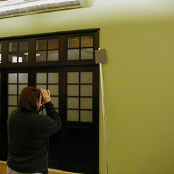
Assess Existing Illuminance
Explore Improvements to Lighting
|
|||||
|
|
|
||||
Methodology: Illuminance MapTo measure the horizontal distribution of illuminance at the height of the task surface (approx. 30 inches), we established a 4 foot grid for data collection points that would remain consistent between each data series. Using Sylvania illuminance meters and a 30" stick base, measurements were taken at each grid point under two different lighting conditions: daylight only (all electric lights off), and daylight plus ambient electric light (overhead lights only; all task lights off). Additionally, we took spot measurements at each desk directly under each operable task light, at the work plane. |
|||||
|
|
|
||||
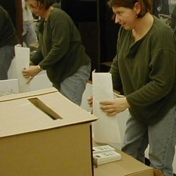
Methodology: Daylighting RedesignSurface reflectance values for surfaces in the space were measured with a Minolta Luminance Meter. A model of the existing space was built at 1/2" = 1'-0" scale, based on construction documents and on-site measurements, including the surface reflectance measurements. In addition to the existing condition, the model was designed to allow the implementation of three other major modifications, both individually and in various combinations. These three modifications are:
In addition to assessing these modifications separately (A, B, C) we
also assessed all the possible combinations of these modifications (AB,
AC, BC, ABC). A total of eight (8) different configurations were modeled
and tested in the Artificial Sky, including the existing configuration.
|
|||||
|
|
|||||