| |
The Ecotrust Building is certainly not new construction - it is a structure
that is on the National Historic Register, has been renovated, and a third
floor has been added on the roof. This combination of factors makes it
very difficult to admit additional daylight into the office space.
- Historic South Facade - no new openings, shading devices, or other
modifications are allowed
- New Third Floor Structure - no toplights may extend more than 16
feet (measured in plan) away from the South or West wall.
One of the problems of attempting a daylighting redesign in this space,
in contrast to designing new construction, is the difficulty of applying
any sort of established design guidelines. In a typical project, design
guidelines would provide a rough idea of the relative performance of
different configurations of apertures in distributing daylight within
the space. For sidelighting, the guideline is presented sectionally
only -- the distance from the window is the determinant of the DF for
a given spot. The guideline does not provide any indication of the way
in which this aperture spreads the light in plan, because the understanding
is that the apertures will be repeated along the wall in such a way
that a uniform DF will be produced. Likewise, the design guidelines
for toplighting are presented specifically for 'typical' apertures,
where the skylights are spaced such that the space is uniformly lit.
therefore, the daylight contribution of a single skylight can not be
readily inferred from these equations.
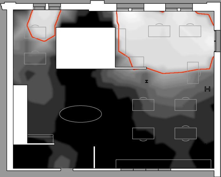
- For example: Applying the 2.5H rule:
- (Usable daylight should penetrate 2.5 times the height of the top
of the window)
- H = 7 feet
Therefore, usable Daylight penetration should therefore be: 2.5 x 7
= 17.5 feet
(slightly more than half the depth of the space)
Judging by the Illuminance Map data, this guideline clearly does not
apply. It is quite likely that this disparity is because of the nonstandard
geometry of the space: there are a limited number of windows, an opaque
freestanding mass in the space, and an abnormally high ceiling that
does little to bounce light back towards the task surface.
The more accurate and communicative way to assess the daylighting characteristics
of unique or singular apertures is in a daylight model -- a small scale
model of the actual space that reproduces the openings, the surface reflectances,
and the major elements within the space. Modifications to the model can
be a highly accurate way to approximate changes made to the actual space,
and the visual presentation of those changes is highly communicative.
|
_t.jpg)
_t.jpg)
_t.jpg)
_t.jpg)
_t.jpg)
_t.jpg)
_t.jpg)
_t.jpg)